Underground observation instrument and underground orientation system

A technology of observation instrument and orientation system, applied in Sagnac effect gyroscope and other directions, can solve the problems of difficult construction, inconvenient reading, reading error, etc., and achieve the effect of less construction difficulty, convenient reading and wide adaptability

Pending Publication Date: 2022-03-04
珠海市泰德企业有限公司
View PDF0 Cites 0 Cited by
  • Summary
  • Abstract
  • Description
  • Claims
  • Application Information

AI Technical Summary

Problems solved by technology

Although this orientation method has reading errors and inconvenience in measurement, it is also a feasible orientation scheme for observation wells within 0 to 300 meters
For observation wells with a height of 500-1000 meters, it is diffic

Method used


Image

  • Underground observation instrument and underground orientation system
  • Underground observation instrument and underground orientation system
  • Underground observation instrument and underground orientation system

Examples


Example Embodiment

[0038] Example 1

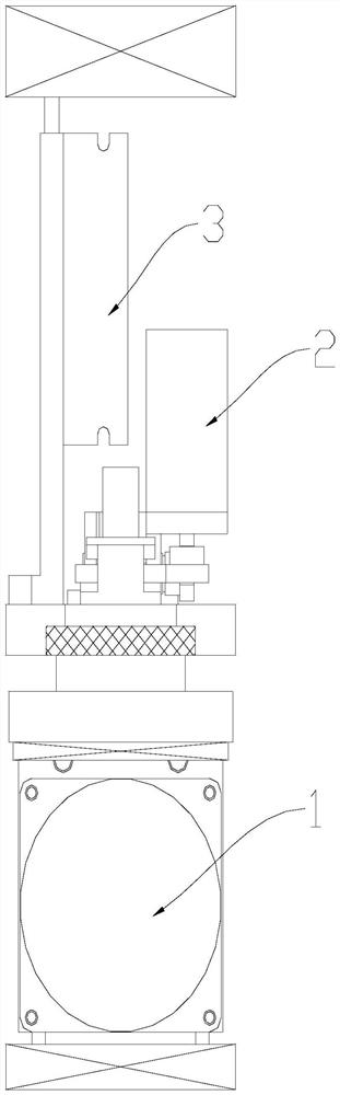
[0039] The invention provides an underground observation instrument, which takes the optical fiber gyroscope 1 as the core, and has the advantages of low construction difficulty, convenient reading and high measurement accuracy.

[0040] like figure 1 As shown, the downhole observation instrument includes a fiber optic gyroscope 1, an angle control structure, and a downhole master control module, and the fiber optic gyroscope 1 collects the optical fiber measurement acceleration value at a specified position in a preset order. The angle control structure is arranged above the fiber optic gyroscope 1 ; the angle control structure is connected to the fiber optic gyroscope 1 . The downhole master control module is connected to the angle control structure, the downhole master control module controls the fiber optic gyroscope 1 to rotate according to a preset angle through the angle control interface, and the downhole master control module receives the data coll...

Example Embodiment

[0063] Embodiment 2

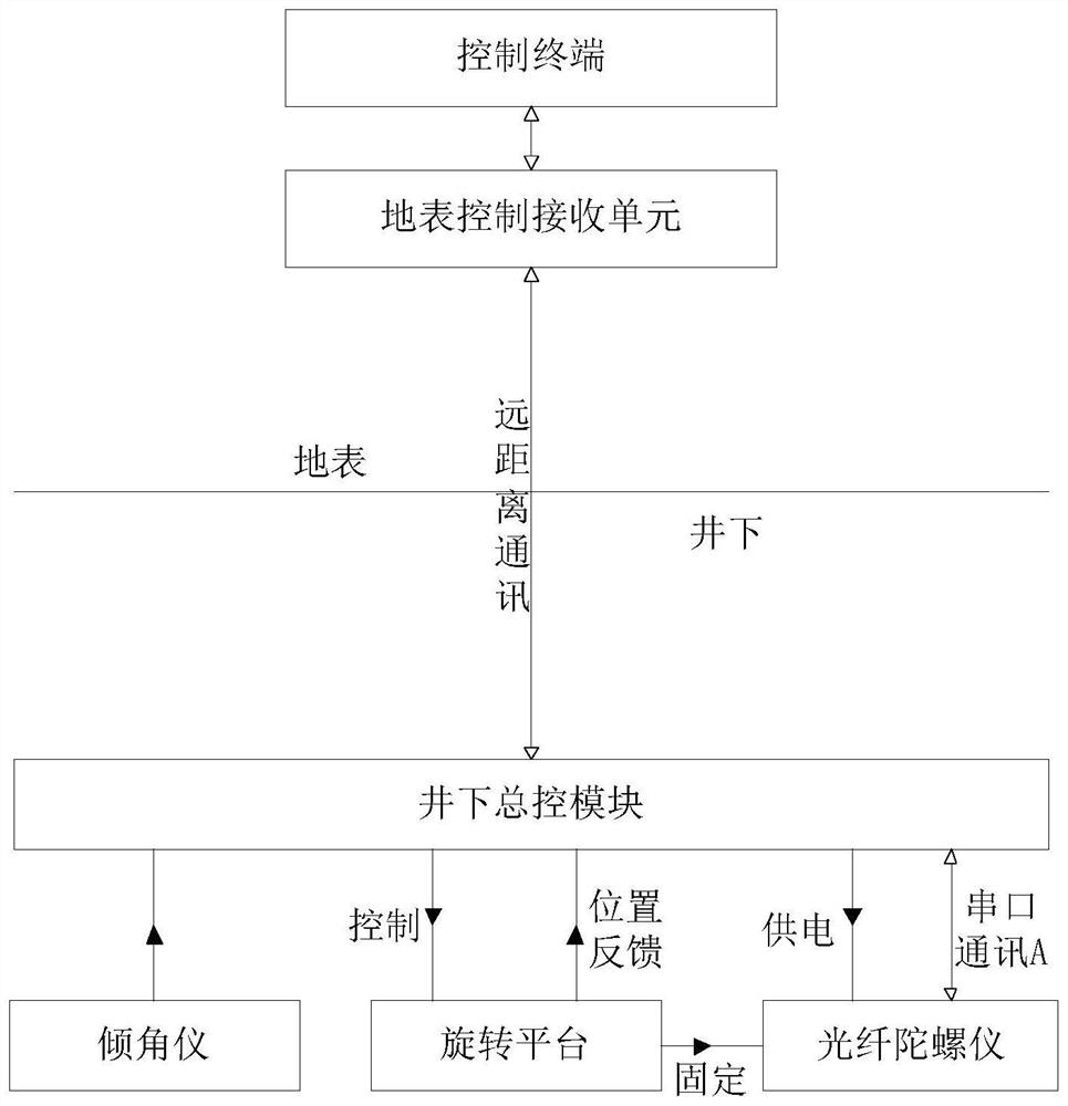
[0064] Based on the same inventive idea, as image 3 As shown, the present invention also provides a downhole orientation system, including the downhole observation instrument, the surface control receiving unit, and the control terminal as described in the first embodiment. The control terminal is used to send out the control command value to the surface control receiving unit, and the surface control receiving unit is connected with the downhole master control module of the downhole observation instrument through a communication module; the surface control receiving unit sends out the orientation through the communication module. The instruction is sent to the downhole master control module to control the downhole observation instrument to measure the azimuth angle, and to receive the azimuth angle sent by the downhole master control module of the downhole observation instrument.

[0065] like Figure 4 As shown, it is a block diagram of the circuit p...


PUM


Abstract

The invention discloses an underground observation instrument and an underground orientation system, and the underground observation instrument comprises an optical fiber gyroscope which collects optical fiber measurement acceleration values at designated positions according to a preset sequence; the angle control structure is arranged above the optical fiber gyroscope; the angle control structure is connected with the optical fiber gyroscope; the underground master control module is connected with the angle control structure, the underground master control module controls the optical fiber gyroscope to rotate according to a preset angle through an angle control interface, and the underground master control module receives an optical fiber measurement acceleration value collected by the optical fiber gyroscope and controls the optical fiber gyroscope to rotate according to the preset angle. And calculating an azimuth angle according to the optical fiber measurement acceleration value and the parameter of the current position. According to the underground measuring instrument and the underground orientation system, the measurement precision is improved, meanwhile, miniaturization of an underground observation instrument is achieved, the construction difficulty is small, reading is convenient, and adaptability is wide.

Description

technical field [0001] The invention relates to the technical field of downhole observation, in particular to an downhole observation instrument and a downhole orientation system. Background technique [0002] Accurately determining the installation orientation of seismic observation instruments is of great significance for the data analysis and application of seismic observation. Fine downhole observation and exploration instruments such as downhole seismometers require precise orientation. However, the traditional downhole instrument orientation methods are not convenient to use and have many restrictions. It is also quite difficult to obtain accurate downhole instrument orientation information. [0003] The installation orientation of underground surface observation is usually determined by means of mechanical compass and compass. But because the volume of mechanical gyroscope and electronic compass is all bigger, and electronic compass is easily subjected to electromagn...

Claims


Application Information

Patent Timeline
IPC IPC(8): G01C19/72
CPCG01C19/72
Inventor 陈洁李丽田鑫罗敏哲赵圣麟罗运宏
Owner 珠海市泰德企业有限公司
Why Eureka
Try Eureka