Self-correlation-based DRM signal identification method under non-ideal channel

A signal identification, non-ideal technology, applied in the baseband system, baseband system parts, digital transmission system, etc., can solve the problem of low accuracy of DRM signal identification, achieve low identification accuracy, improve identification accuracy, and solve the problem of identification difficult effect

Pending Publication Date: 2022-03-04
HARBIN INST OF TECH
View PDF0 Cites 2 Cited by
  • Summary
  • Abstract
  • Description
  • Claims
  • Application Information

AI Technical Summary

Problems solved by technology

[0006] The purpose of the present invention is to solve the problem of low recognition accuracy of existing DRM signals transmitted through ionospheric channels, and propose a DRM signal recognition method based on autocorrelation under non-ideal channels

Method used


Image

  • Self-correlation-based DRM signal identification method under non-ideal channel
  • Self-correlation-based DRM signal identification method under non-ideal channel
  • Self-correlation-based DRM signal identification method under non-ideal channel

Examples


specific Embodiment approach 1

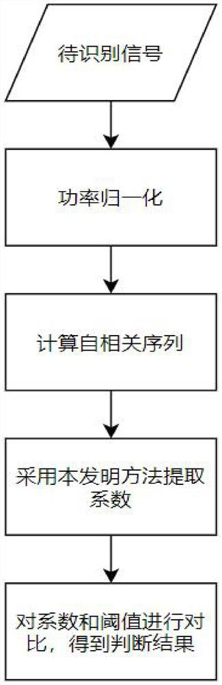
[0028] Specific implementation mode 1: In this implementation mode, a specific process of a DRM signal identification method based on autocorrelation in a non-ideal channel is as follows:

[0029] Step 1: Select the data recorded by the IQ dual-channel receiver, and record the selected time domain signal as X(t);

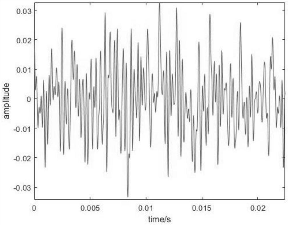
[0030] Step 2: Normalize the time-domain signal X(t) selected in Step 1 to obtain a normalized signal The time domain waveform of the signal is obtained as figure 2 shown;

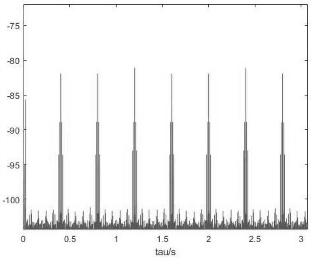
[0031] Step 3: Calculate the normalized signal The autocorrelation function R(τ), the value range of the autocorrelation delay τ is not less than [-1.5T frame ,1.5T frame ](The value range of autocorrelation delay τ must at least include the mentioned interval. For example, the range is not less than [-1.5,1.5], then the actual range can be [-2,2], but not [-1 ,1]); the processing result is as follows image 3 shown;

[0032] Step 4: Select an appropriate threshold value Thd3, compare ...

specific Embodiment approach 2

[0039] Specific embodiment two: what this embodiment is different from specific embodiment one is that, in described step one, the data that IQ dual-channel receiver is taken in is selected, and the time domain signal that selects is denoted as X (t); Concrete process for:

[0040] Select the data recorded by the IQ dual-channel receiver, and the time length of the selected data is greater than the transmission frame time length of the two DRM signals;

[0041] The transmission frame time length of the DRM signal is T frame .

[0042] Other steps and parameters are the same as those in Embodiment 1.

specific Embodiment approach 3

[0043] Embodiment 3: The difference between this embodiment and Embodiment 1 or 2 is that in the step 2, the time domain signal X(t) selected in the step 1 is normalized to obtain a normalized signal The time domain waveform of the signal is obtained as figure 2 Shown; the specific process is:

[0044] Step 21: Find the time mean value of X(t), record the time mean value as m X ;

[0045] Step 22: Find the standard deviation of X(t), record the standard deviation as σ X ;

[0046] Step two and three: based on the time mean m X and standard deviation σ X , to obtain the normalized signal X(t).

[0047] Other steps and parameters are the same as those in Embodiment 1 or Embodiment 2.


PUM


Abstract

The invention discloses a DRM signal identification method under a non-ideal channel based on autocorrelation, and relates to a DRM signal identification method under a non-ideal channel. The objective of the invention is to solve the problem of low recognition accuracy of DRM signals transmitted through an ionized layer channel in the prior art. The method comprises the following steps: 1, obtaining a time domain signal; 2, performing normalization processing on the time domain signal; 3, calculating an autocorrelation function of the normalized signal; 4, selecting a threshold value, comparing the threshold value with the autocorrelation function, reserving values greater than or equal to the threshold value in the autocorrelation function, and setting values less than the threshold value to zero; 5, obtaining a coefficient cdt1; 6, obtaining a coefficient cdt2; 7, selecting a threshold value Thd1 and a threshold value Thd2, and if the cdt1 and the cdt2 are respectively greater than the Thd1 and the Thd2, judging that the selected time domain signal is a DRM signal; otherwise, judging that the selected time domain signal is not the DRM signal. The method is used in the field of signal classification and identification.

Description

technical field [0001] The invention relates to the field of signal classification and identification and the field of short-band passive radar signal processing, and can be used for the identification of DRM signals under non-stationary channel conditions. Background technique [0002] Passive radar uses electromagnetic signals emitted by a third party for target detection, and has unique advantages such as low construction and maintenance costs; strong concealment; saving spectrum resources; rich types of irradiation sources, wide distribution, and few radiation blind spots. Passive radar is an important member of the new system radar. For passive radar, finding the waveform of the radiation source suitable for radar detection in the electromagnetic environment is the first problem to be solved, and the accurate identification of the radiation source is the key problem in passive radar. [0003] Digital AM broadcasting (Digital Radio Mondiale, DRM) was standardized by ETS...

Claims


Application Information

Patent Timeline
Patent Type & Authority Applications(China)
IPC IPC(8): H04L25/02
CPCH04L25/0238
Inventor 耿钧张弓常蒙李浩然
Owner HARBIN INST OF TECH
Why Eureka
Try Eureka