Measuring device, measuring system and measuring method
A measurement device and measurement system technology, applied in the field of medical devices, can solve the problems of inaccurate measurement results and the like
- Summary
- Abstract
- Description
- Claims
- Application Information
AI Technical Summary
Problems solved by technology
Method used
Image

Examples
Embodiment approach 1
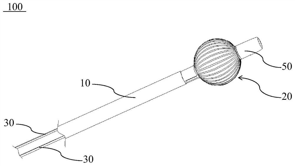
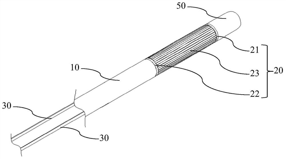
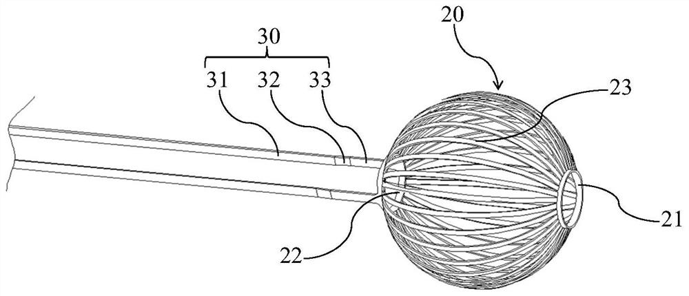
[0058] combine figure 1 and figure 2 As shown, the measuring device 100 of this embodiment includes a catheter 10 and a mapping element 20. The catheter 10 is a hollow tubular structure, and its interior is used for passing components such as guide wires. The marker 20 is deformably sleeved on a part of the outer surface of the distal end of the catheter 10, and the marker 20 can be deformed by itself or driven by an external driver, so that the marker 20 has a shape of a true sphere or is close to a true sphere The working state of the shape is used for measurement, and the marking part 20 has developability at least when it is in the shape of a true sphere or close to the shape of a true sphere. The marking part 20 can be made of superelastic metal alloy material or polymer material, such as nickel-titanium alloy, cobalt-chromium alloy, etc., and X-ray developable materials can also be uniformly added to these materials, such as BaSO4, ( BIO) 2 CO 3 Etc., in order to en...
Embodiment approach 2
[0073] Parts in the second embodiment that are the same as or similar to those in the first embodiment will not be repeated here. combine Figure 9 and Figure 10 As shown, the measuring device 100 of this embodiment includes a catheter 10 , a mapping element 20 and a sheath 40 . Wherein, the catheter 10 is passed through the sheath tube 40 and the distal end of the catheter 10 protrudes from the distal end of the sheath tube 40 . The distal end of the sheath tube 40 is connected to the proximal end of the marker 20 , and the distal end of the catheter 10 is connected to the distal end of the marker 40 .
[0074] combine Figure 10 , Figure 11 and Figure 12 As shown, when the marker 20 of this embodiment is in a contracted state, a plurality of support rods 23 are helically spaced around the central axis of the catheter 10 and surround the outer surface of the distal end of the catheter 10 . Each support rod 23 is arranged at equal intervals along the circumferential d...
Embodiment approach 3
[0080] Parts in the third embodiment that are the same as or similar to those in the second embodiment will not be repeated here. The measuring device of this embodiment is basically the same as that of Embodiment 2, the difference lies in that the marker 20 of this embodiment has better elasticity. When the marker 20 is in the delivery process, it is compressibly accommodated between the sheath tube 40 and the catheter 10, and when the marker 20 protrudes from the distal end of the sheath tube 40 to break away from the constraint of the sheath tube 40, it expands and expands to be in the In the working state, at this time, the mapping part 20 is in the shape of a true sphere or close to a shape of a true sphere. The developability of the marking member 20 can be realized by its own material, or it can be developed under DSA with the assistance of other developable materials.
[0081] combine Figure 13 and Figure 14 As shown, in one implementation of this embodiment, the ...
PUM
 Abstract
Description
Claims
Application Information
 - R&D
- Intellectual Property
- Life Sciences
- Materials
- Tech Scout
- Unparalleled Data Quality
- Higher Quality Content
- 60% Fewer Hallucinations
Browse by: Latest US Patents, China's latest patents, Technical Efficacy Thesaurus, Application Domain, Technology Topic, Popular Technical Reports.
© 2025 PatSnap. All rights reserved.Legal|Privacy policy|Modern Slavery Act Transparency Statement|Sitemap|About US| Contact US: help@patsnap.com