Rod bending device for orthopedic spinal operation connecting rod and forming method

A technology of connecting rods and bending rods, applied in the directions of internal bone synthesis, fixator, internal fixator, etc., can solve the problems of complicated operation, damage to the spinal cord and nerve of patients, time-consuming and laborious, and achieve the effect of simple and convenient operation.

Pending Publication Date: 2022-03-08
付兆宗
View PDF2 Cites 0 Cited by
  • Summary
  • Abstract
  • Description
  • Claims
  • Application Information

AI Technical Summary

Problems solved by technology

[0004] However, the above-mentioned rod benders all have the following disadvantages: (1) the accuracy is poor, because there are few stress points on the connecting rod, the angle after bending can only be determined by the doctor's experience, and there is a large error; (2) there is no reproducibility and Conformity, because the current arc cannot be controlled and measured during the bending operation, even if the preoperative doctor plans a good arc according to the imaging data, the traditional rod bender cannot make a connecting rod that meets the preoperative plan;( 3) There is no continuity, time-consuming and labor-intensive. Due to the small opening of the rod bender, it is impossible to form a long connecting rod at one time. When the operation range is large (more than 2 segments), it is necessary to move the rod bender repeatedly, resulting in Complicated and time-consuming; (4) It is impossible to accurately realize the "S"-shaped bending rod. For patients with scoliosis or severe osteoporosis, long-segment surgery usually involves two or two physiological bends, and the connecting rod needs to be completed "S" The bending direction of the current rod bender is single. Even if the analog rod is used as a reference, it is difficult to accurately bend the rod into the required arc. Repeated operations are required, which reduces the stiffness of the connecting rod and increases postoperative nail breakage. Risk of rod or internal fixation loosening; (5) Poor grip strength and easy slipping. Currently, the rod bender tends to slip or even pop out when bending a short rod, which may injure the operator, or damage the patient's spinal cord and nerves, affecting function
[0005] Therefore, it is necessary to design a rod bender that can accurately bend rods, continuously bend rods, save time and effort, is safe and can be formed at one time to overcome the disadvantages of poor precision, repeated operations, and easy slipping when bending rods in the prior art.

Method used


Image

  • Rod bending device for orthopedic spinal operation connecting rod and forming method
  • Rod bending device for orthopedic spinal operation connecting rod and forming method
  • Rod bending device for orthopedic spinal operation connecting rod and forming method

Examples


Embodiment Construction

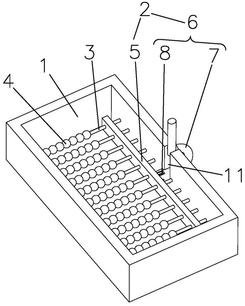
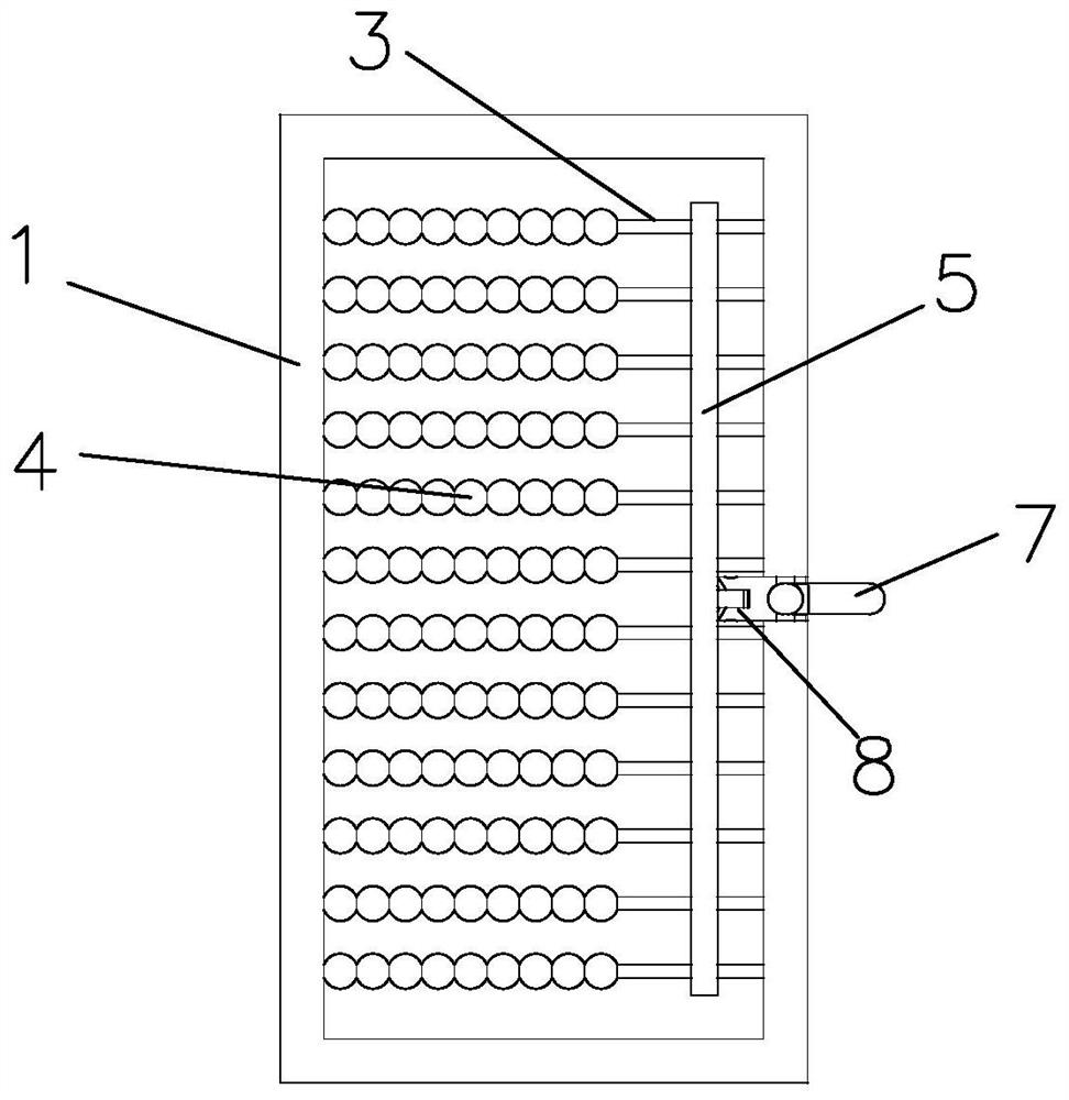
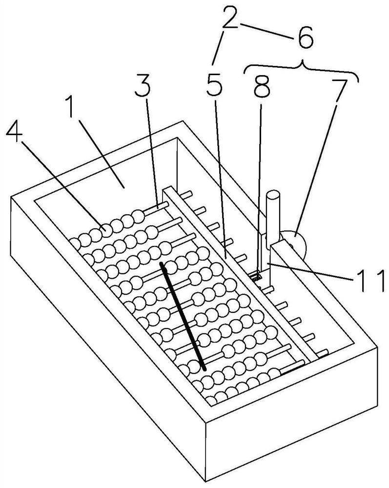
[0033] refer to figure 1 , figure 2 A rod bender for connecting rods in orthopedic spinal surgery, comprising a rigid frame bearing tray 1, a bending assembly 2, a sliding rod 3 and a sliding member 4, the rigid frame loading tray 1 has a rectangular metal frame, and the bending assembly 2 It includes a pressing plate 5 vertically arranged with the sliding rod 3 and a driving mechanism 6 that drives the pressing plate 5 to slide toward the sliding part 4; the sliding rod 3 is a metal rod with a smooth surface and has a plurality of parallel erected in the rigid frame carrying plate 1 to form a fence According to the same structure, each sliding rod 3 is pierced with a set of sliding parts 4, and when the volume of the sliding parts 4 is smaller, the more and more densely the sliding rods 3 are arranged, the higher the accuracy of the bending rod.

[0034] Normally, the sliders 4 are arranged on the same side of the rigid frame carrying plate 1 to form an array, and the press...


PUM


Abstract

The invention discloses a bar bending device and a forming method for an orthopedic spinal operation connecting bar, the bar bending device comprises a rigid frame bearing disc, a bending assembly, a plurality of sliding rods and sliding pieces, the sliding rods are parallelly erected in the rigid frame bearing disc, each sliding rod is provided with a set of sliding pieces in a penetrating mode, and the bending assembly is arranged on the rigid frame bearing disc; the sliding pieces in each group have the same length and are positioned on the same side to form an array; the bending assembly comprises a top pressing plate and a driving mechanism. When the connecting rod is bent, the sliding parts are shifted along the sliding rod by changing the distribution of the sliding part array, a gap is formed between the sliding parts on the two sides, and the radian needed by the connecting rod is defined by the edge of the gap; a connecting rod blank is placed in the gap, the top pressing plate is driven by the driving mechanism to push the sliding pieces to synchronously move to achieve resetting of the sliding pieces on the two sides, the bending radian is more accurately controlled through the multi-point rod bending principle, one-time pressing forming is directly achieved through the sliding pieces, and operation is easy and convenient. And the connecting rod is supported on the rod bending device and is clamped by multiple points, so that the clamping effect is good, and the connecting rod is not easy to slip off and pop up.

Description

technical field [0001] The invention relates to the field of medical equipment, in particular to a rod bender and a bending method applied to orthopedic spinal surgery for bending connecting rods. Background technique [0002] Screw-and-rod technique (pedicle screw fixation, vertebral body screw fixation, etc.) is the most commonly used technique in spinal surgery. After the screw is implanted, the physiological curvature of the spine is restored or the deformity is corrected by placing a connecting rod with an appropriate curvature. Therefore, how to use the rod bender to bend the connecting rod into a suitable arc is very critical. [0003] The most common in the prior art is the rod bender of the three-point principle, such as a rod bender disclosed in the utility model patent of the patent announcement number CN205913389U, which includes a pair of long arms, a pivot and a bending assembly. On the basis of the rod principle, an arc-shaped measuring ruler is added, and t...

Claims


Application Information

Patent Timeline
IPC IPC(8): A61B17/88A61B17/70
CPCA61B17/8863A61B17/7002A61B17/7074
Inventor 付兆宗司沙沙陈忠羡
Owner 付兆宗
Why Eureka
Try Eureka