O-shaped rubber ring assembling equipment and assembling method thereof

A technology for assembling equipment and rubber rings, which is applied in assembly machines, metal processing equipment, metal processing, etc., can solve the problems of low assembly efficiency of rubber rings, and achieve the effect of efficient, accurate press fitting and volume reduction in the assembly process.

Pending Publication Date: 2022-03-08
YANGZHOU MEDLINE IND CO LTD
View PDF1 Cites 0 Cited by
  • Summary
  • Abstract
  • Description
  • Claims
  • Application Information

AI Technical Summary

Problems solved by technology

[0005] The invention provides an O-shaped rubber ring assembly equipment to solve the problem of low rubber ring assembly efficiency

Method used


Image

  • O-shaped rubber ring assembling equipment and assembling method thereof
  • O-shaped rubber ring assembling equipment and assembling method thereof
  • O-shaped rubber ring assembling equipment and assembling method thereof

Examples


Embodiment 1

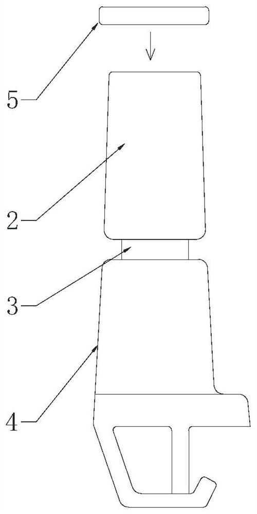
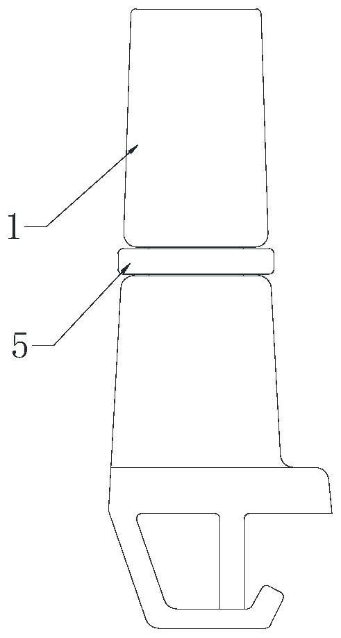
[0043] Such as Figure 1 to Figure 7 As shown, an O-shaped rubber ring assembly equipment is used to assemble the rubber ring 5 on the tubular part 1, such as infusion joints, but not limited to infusion joints, and can also be other products with similar structures, please refer to figure 1 and figure 2 , the tubular part 1 includes an upper tube body 2, a limiting part 3 and a lower clamp seat 4 integrally formed from top to bottom in sequence, the upper tube body 2 is a tapered cylinder gradually expanding from top to bottom, and the limiting part 3 is The ring shape shrinks inwardly from the bottom of the upper tube body 2 , and the rubber ring 5 needs to be assembled on the stopper 3 .

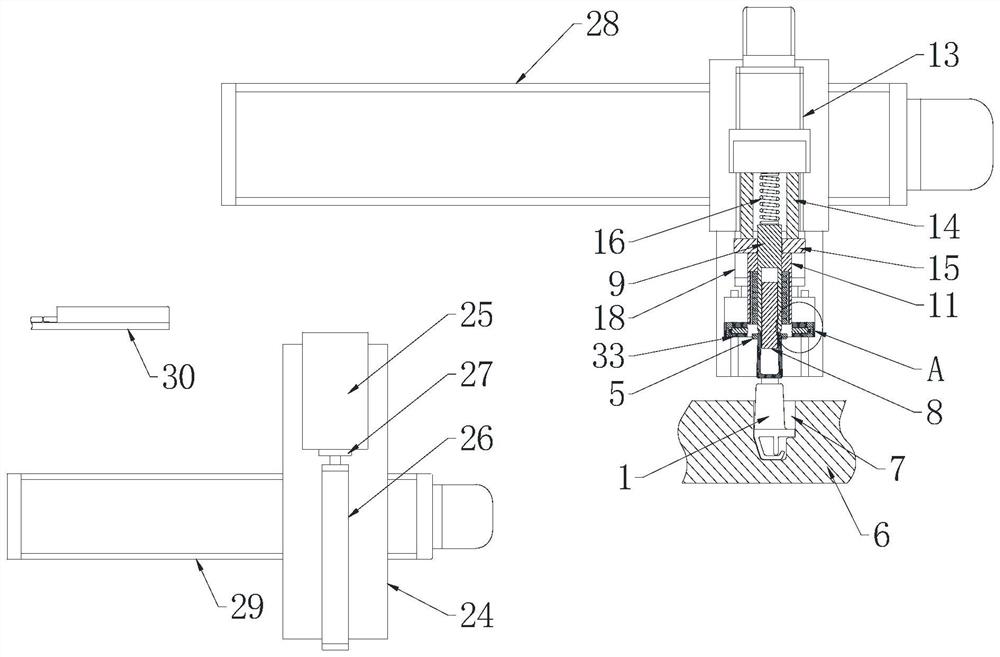
[0044] Such as image 3 As shown, the O-ring rubber ring assembly equipment includes: a conveying mechanism and a press-fitting mechanism.

[0045] The conveying mechanism 6 is used for intermittently conveying the tubular parts to the press-fitting mechanism. A plurality of positioni...

Embodiment 2

[0064] In this embodiment, on the basis of Embodiment 1, a feeding mechanism is also provided for automatically supplying the rubber ring 5 to the hair ring body 11 . Such as Figure 6 and Figure 7 As shown, the feeding mechanism includes a support plate 24 vertically installed on the frame, on which the feed bin 25 and the third lift driver 26 are fixedly installed, and the third lift driver 26 can be selected from a pen-shaped cylinder or other realizable Drives for linear motion. The storehouse body of feed bin 25 is all exposed up and down, and a row of rubber rings 5 ​​is accommodated in the storehouse body along the vertical direction, and the third lift driver 26 is positioned at the below of feed bin 25, and top block 27 is installed on its piston rod, and the diameter of top block 27 Slightly less than the outer diameter of the rubber ring 5, to push up the rubber ring in the warehouse body until it is tightly placed on the slide pipe 9 directly above it. Wherein,...


PUM


Abstract

The invention provides O-shaped rubber ring assembling equipment and an assembling method thereof.The O-shaped rubber ring assembling equipment comprises a conveying mechanism used for intermittently conveying tubular parts, the tubular parts are positioned on the conveying mechanism, and pipe openings of the tubular parts face upwards; the press-fitting mechanism is used for press-fitting the rubber ring on the tubular part, and the press-fitting mechanism comprises a pre-pressing mechanism and an assembling mechanism which are matched with each other; the assembling mechanism comprises a pressing plate used for pressing the rubber ring at the end of the tubular part into the assembling position, and the pressing plate is driven by a second lifting driving piece to move up and down. Fast-beat continuous feeding and assembling can be achieved, and the assembling efficiency is high.

Description

technical field [0001] The invention relates to an O-shaped rubber ring assembly device and an assembly method thereof. Background technique [0002] O-shaped rubber rings are often used for sealing connections between parts. For example, rubber rings need to be installed on infusion joints to effectively seal the joints and prevent liquid seepage. [0003] Existing O-shaped rubber rings are all automatically assembled using a press-fitting machine. For example, the patent with the publication number CN208772924U discloses an assembly system for O-shaped sealing rings and hollow parts. The O-ring is transported to the groove by the O-ring vibrating plate Inside, the drive cylinder drives the O-ring placement plate to send the O-ring to the matching hole, the second cylinder drives the connecting rod to insert into the matching hole, the first driving source drives the connecting rod to move above the through hole; the parts vibrating plate conveys the parts When the vertica...

Claims


Application Information

Patent Timeline
Patent Type & Authority Applications(China)
IPC IPC(8): B23P21/00B23P19/027B23P19/00
CPCB23P21/004B23P19/027B23P19/001B23P19/002B23P19/007
Inventor 祁建忠谭伟
Owner YANGZHOU MEDLINE IND CO LTD
Why Eureka
Try Eureka