Plastic mold cutting device
A technology for cutting devices and plastic molds, applied in positioning devices, manufacturing tools, clamping, etc., can solve problems such as inability to fix molds, and achieve the effects of improving protection, improving practicability, and improving stability
- Summary
- Abstract
- Description
- Claims
- Application Information
AI Technical Summary
Problems solved by technology
Method used
Image
Examples
Embodiment 1
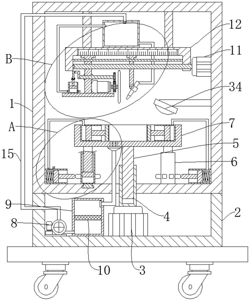
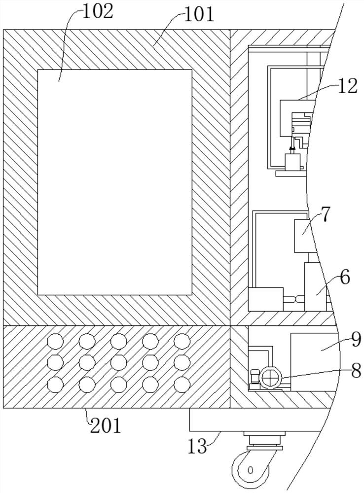
[0030] Refer Figure 1-7 One plastic mold cutting device includes a working case 1, a device case 2, a base 13, and a working case 1 fixed to the apparatus box 2, and the equipment case 2 is fixed to the base 13, and the fixing connection is fixed in the equipment case 2. The motor 3, the output end of the first motor 3 fixes the connection to the cylinder 4, and the cylinder 4 is rotated by the thread, and the upper end of the threaded rod 5 runs through the working box 1, and the fixed connection is placed 7, threaded A sleeve 6 is provided on both sides of the rod 5, and the sleeve 6 is rotated between the working case 1, and the sleeve 6 is rotatably connected to the finite column 17, and the upper end of the limit column 17 is fixed to the placement table 7, and the table 7 is fixed. A clamping mechanism is provided on both sides, and the lower ends of the working case 1 are provided with an inflatable mechanism that matches the clamping mechanism, and the sleeve 6 is connecte...
Embodiment 2
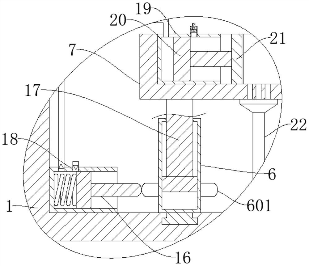
[0033] Refer figure 1 and image 3 , A plastic mold cutting device is substantially the same as in Example 1, and further: the clamping mechanism includes a first cylinder 19, a first piston 20, and two first cylinders 19 are fixed to both ends of the placed table 7, respectively. The first piston 20 is slidked within the first cylinder 19, and the first piston 20 is fixed from one end of the first cylinder 19, and the jet plate 21 is fixed, the inflatable mechanism includes a second cylinder 18, a second piston 16, a spring, two The second cylinder 18 is fixed to both sides of the lower end of the working order 1, and the spring is fixedly coupled to the second cylinder 18, and the second piston 16 is slidably coupled to the second cylinder 18, and is connected to the spring, the second piston 16 away from the spring. One end matches the circular arc bump 601, and the air opening of the second cylinder 18 is connected to the intake port of the first cylinder 19, and when the place...
Embodiment 3
[0035] Refer figure 1 and Figure 4 One plastic mold cutting device is substantially the same as in Example 1, further in the case where the cutting mechanism includes a third motor 27, a cutting wheel 29, and a cutting wheel 29 fixed to the output shaft of the third motor 27, a third motor. The first gear is fixedly connected to the output shaft of 27, and the pressurizing mechanism includes the third cylinder 31, the third piston 32, and the third piston 32 is slidably connected to the third cylinder 31, and the first mobile rod 25 rotates the connection rod. 28, the connecting rod 28 is fixed to one end of the cutting wheel 29, and the second gear of the first gear is fixed, and the connecting rod 28 is rotated from one end of the second gear to the connection column, and the connection post is rotated between the third piston 32. The air port of the third cylinder 31 and the air opening of the water tank 33 are connected by the second trachea, and the inlet and outlet port of t...
PUM
 Abstract
Description
Claims
Application Information
 - R&D
- Intellectual Property
- Life Sciences
- Materials
- Tech Scout
- Unparalleled Data Quality
- Higher Quality Content
- 60% Fewer Hallucinations
Browse by: Latest US Patents, China's latest patents, Technical Efficacy Thesaurus, Application Domain, Technology Topic, Popular Technical Reports.
© 2025 PatSnap. All rights reserved.Legal|Privacy policy|Modern Slavery Act Transparency Statement|Sitemap|About US| Contact US: help@patsnap.com


