A horizontal conveying device

A material conveying and horizontal technology, applied in the direction of conveyor control device, transportation and packaging, conveyor objects, etc., can solve the problem of low accuracy of material position, and achieve high manufacturing precision requirements, high work reliability, and accurate realization The effect of control

Active Publication Date: 2022-04-26
秦皇岛优益创联特种车辆制造有限公司
View PDF0 Cites 0 Cited by
  • Summary
  • Abstract
  • Description
  • Claims
  • Application Information

AI Technical Summary

Problems solved by technology

[0005] The invention proposes a horizontal conveying device, which solves the problem that the accuracy of the material position is not high when the conveying device in the related art conveys the material

Method used


Image

  • A horizontal conveying device
  • A horizontal conveying device
  • A horizontal conveying device

Examples


Embodiment 1

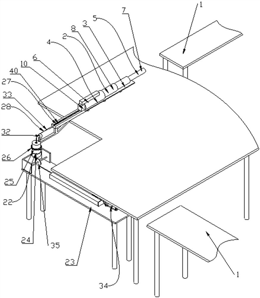
[0058] Such as Figure 1~Figure 4 As shown, this embodiment proposes a horizontal material conveying device, which can solve the problem of low material position accuracy when the material is conveyed by the conveying device in the related art. This embodiment is suitable for precisely adjusting the pushing position of the length without adjustment Situation of pushing angle.

[0059] The specific structure is as follows:

[0060] It includes a feeding platform 1 and a pushing device 2 arranged on one side of the feeding platform 1, the pushing device 2 is used to push the material on the feeding platform 1, and the support 3 of the pushing device 2 is fixed on the ground;

[0061] The structure of the pushing device 2 is composed of several telescopic arms 5 with different diameters. The expansion and contraction of the telescopic arms 5 is driven by the rigid chain 9, and the telescopic direction is along the horizontal direction. Other directions can also be implemented, b...

Embodiment 2

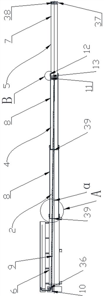
[0069] Such as Figure 1~Figure 5 As shown, this embodiment proposes a horizontal conveying device. On the basis of Embodiment 1, a mechanism capable of positioning the rigid chain 9 is added to further better solve the problem that the rigid chain 9 is heavy due to gravity during long-distance transmission. , Affected by gravity, the phenomenon of "slumping waist" appears.

[0070] Specifically, the structure adopted by the mechanism for positioning the rigid chain 9 is as follows:

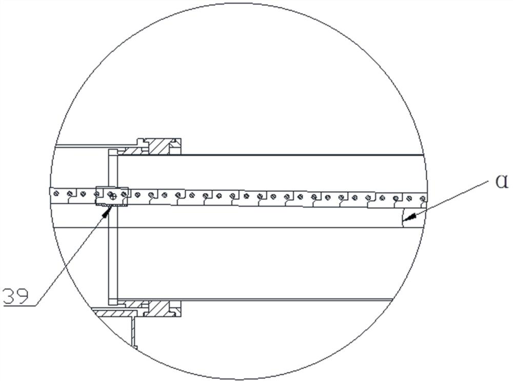
[0071] A position sensor 13 is arranged between the first protrusion 11 of one telescopic arm 5 and the second protrusion 12 of the other telescopic arm 5. When a telescopic arm 5 walks toward the direction of pushing materials, the walking telescopic arm 5 will The first protrusion 11 of the first telescopic arm 5 gradually approaches the second protrusion 12 on the rear telescopic arm 5 until the first protrusion 11 and the second protrusion 12 clamp the position sensor 13, and the first protr...

Embodiment 3

[0075] Such as Figure 1~Figure 5 As shown, this embodiment proposes a horizontal conveying device, and on the basis of Embodiment 2, a specific mechanism of the locking mechanism 14 is provided.

[0076] Specifically, the structure adopted by the locking mechanism 14 is as follows:

[0077] The clamp assembly 16 for clamping the rigid chain 9 is divided into a fixed first clamp 17 and a movable second clamp 18, the movement of the second clamp 18 is driven by the clamp drive 15, and the clamp drive 15 The opening and closing of the valve is affected by the signal of the position sensor 13.

[0078] The rigid chain 9 moves against the first clip 17, and the second clip 18 is moved and arranged in the telescopic arm 5 by means of the clamping drive device 15. The second clip 18 and the first clip 17 are respectively located on both sides of the rigid chain 9, After the second clip 18 moves, the second clip 18 and the first clip 17 clamp the rigid chain 9 in the horizontal dir...


PUM


Abstract

The invention relates to the technical field of material conveying, and proposes a horizontal material conveying device, including a material conveying platform and a pushing device arranged on one side of the material conveying platform, the pushing device is used to push materials on the material conveying platform, and the pushing device includes a The telescopic part on the support, the telescopic part includes several telescopic arms with different diameters, the telescopic arm with the largest diameter is the connecting arm, the telescopic arm with the smallest diameter is the push arm, and the other telescopic arms are the transmission arms, the first driving mechanism passes through the sprocket After driving the rigid chain to move, the encoder collects the rotation information of the sprocket, the rigid chain drives the push arm and the transmission arm to move in sequence, the rigid chain extends in the horizontal downward direction, and the brackets are rotated and set at the end of the telescopic direction of the telescopic arms at all levels , the rigid link is lapped on the bracket, and the push plate is arranged at the end of the push arm through a push-pull force sensor. The above technical solution solves the problem of low material position accuracy when the material is transported by the conveying device in the related art.

Description

technical field [0001] The invention relates to the technical field of material conveying, in particular to a horizontal conveying device. Background technique [0002] In many actual production scenarios, it is necessary to transport the product to the predetermined location, so the conveying device is an indispensable equipment in the field of industrial production, and its reliability, operability and efficiency are very important. [0003] In the prior art, the feeding device has various forms, including rope-row type, oil cylinder type and automatic plug-in type, etc. There are elastic deformation and permanent elongation and deformation of the steel wire rope used in the rope-row type expansion device during the working process, so that the protruding position cannot be accurately monitored, and it is not suitable for use in occasions with high precision requirements; the oil cylinder type expansion device is used In the process, the protruding position is uncontrolla...

Claims


Application Information

Patent Timeline
Patent Type & Authority Patents(China)
IPC IPC(8): B65G47/82B65G43/00
CPCB65G47/82B65G43/00
Inventor 覃艳明王卫张晓刚张胜伟郑海洋贾强乐王秀杰郭欣王向南刘沙沙
Owner 秦皇岛优益创联特种车辆制造有限公司
Why Eureka
Try Eureka