
Aircraft engine turbine disc cavity gas collecting and flow guiding structure

A technology for aero-engines and turbine disks, applied to engine components, machines/engines, mechanical equipment, etc., can solve problems such as intrusion and complex structure design of turbine guides, and achieve the effect of simplifying structural design and manufacturing

Active Publication Date: 2022-03-08
AECC SICHUAN GAS TURBINE RES INST
View PDF10 Cites 0 Cited by
  • Summary
  • Abstract
  • Description
  • Claims
  • Application Information

AI Technical Summary

Problems solved by technology

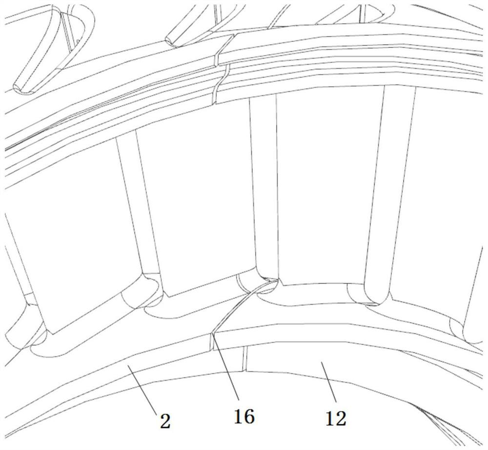
[0002] Aeroengine turbine guides are generally annular structures formed by a certain number of multi-blades or single blades matched in the circumferential direction. There will be gaps between the matching surfaces of the lower edge plates of adjacent blades in the circumferential direction that constitute the turbine guide. For small and low-cost For aero-engines, setting a special sealing structure between the mating surfaces of the lower edge plates of the turbine guide blades (referred to as turbine guide vanes) will make the structural design of the turbine guide too complicated, and considering the manufacturing cost, small and low-cost aero-engine turbines No special sealing structure will be designed at the gap of the lower edge plate of the guide vane
[0003] However, for the high-pressure turbine, the gas in the main channel of the turbine guide will invade the front cavity of the high-pressure turbine disk through the gap of the lower edge plate of the turbine vane.

Method used


Image

  • Aircraft engine turbine disc cavity gas collecting and flow guiding structure
  • Aircraft engine turbine disc cavity gas collecting and flow guiding structure
  • Aircraft engine turbine disc cavity gas collecting and flow guiding structure

Examples


Embodiment Construction

[0022] Embodiments of the present disclosure will be described in detail below in conjunction with the accompanying drawings.

[0023] Embodiments of the present disclosure are described below through specific examples, and those skilled in the art can easily understand other advantages and effects of the present disclosure from the contents disclosed in this specification. Apparently, the described embodiments are only some of the embodiments of the present disclosure, not all of them. The present disclosure can also be implemented or applied through different specific implementation modes, and various modifications or changes can be made to the details in this specification based on different viewpoints and applications without departing from the spirit of the present disclosure. It should be noted that, in the case of no conflict, the following embodiments and features in the embodiments can be combined with each other. Based on the embodiments in the present disclosure, a...


PUM


Abstract

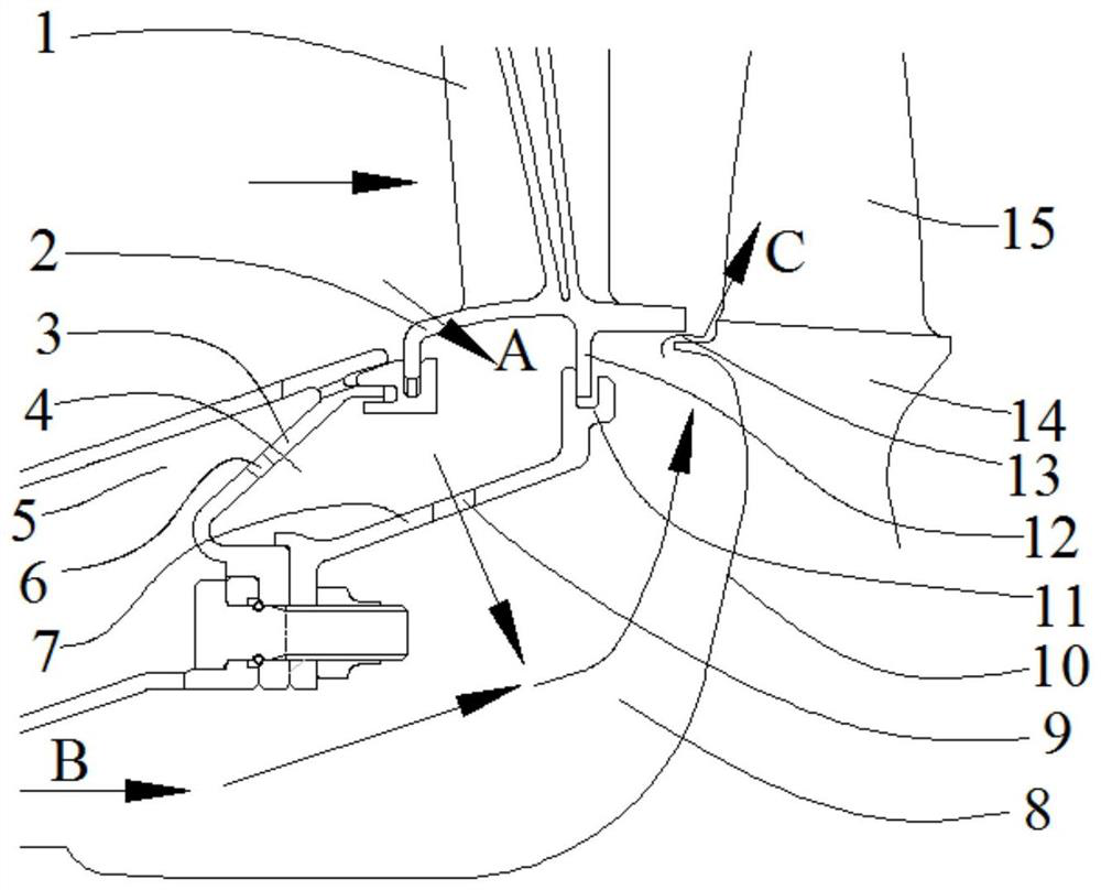
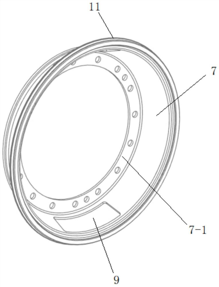
The invention provides an aero-engine turbine disc cavity gas collecting and flow guiding structure which comprises a semi-closed turbine disc cavity composed of a high-pressure turbine guide vane lower margin plate, a high-pressure turbine blisk front side disc face and a combustion chamber flame tube inner supporting ring and further comprises a gas collecting and flow guiding box which is of an annular structure on the whole and comprises an annular side wall. The edges of the two sides of the annular side wall extend to form a rear end connecting edge and a front end connecting edge respectively, the rear end connecting edge of the gas collecting and flow guiding box is fixedly connected with a high-pressure turbine guide vane lower edge plate, and the front end connecting edge of the gas collecting and flow guiding box is fixedly connected with a combustion chamber flame tube inner supporting ring. An annular gas collection cavity is formed among the gas collection flow guide box, the combustion chamber flame tube inner supporting ring and the high-pressure turbine guide vane lower edge plate. According to the invention, the influence of high-temperature gas entering the disc cavity on the temperature of the turbine disc cavity and the influence of gas in the disc cavity on the temperature of turbine moving blades after entering a turbine runner can be effectively reduced.

Description

technical field [0001] The present disclosure relates to the technical field of aero-engines, and in particular to an aero-engine turbine disk cavity air-collecting and guiding structure. Background technique [0002] Aeroengine turbine guides are generally annular structures formed by a certain number of multi-blades or single blades matched in the circumferential direction. There will be gaps between the matching surfaces of the lower edge plates of adjacent blades in the circumferential direction that constitute the turbine guide. For small and low-cost For aero-engines, setting a special sealing structure between the mating surfaces of the lower edge plates of the turbine guide blades (referred to as turbine guide vanes) will make the structural design of the turbine guide too complicated, and considering the manufacturing cost, small and low-cost aero-engine turbines No special sealing structure will be designed at the gap of the lower edge plate of the guide vane. [...

Claims


Application Information

Patent Timeline
Patent Type & Authority Applications(China)
IPC IPC(8): F01D9/04F01D25/12F01D25/00
CPCF01D9/041F01D25/12F01D25/00Y02T50/60
Inventor 王鹏飞李天禄李超王永红陈凯
Owner AECC SICHUAN GAS TURBINE RES INST
Learn More