
Device and method for monitoring tower stability and filling soil hole in karst development area

A development area and monitoring rod technology, applied in the field of geotechnical engineering, can solve the problems of difficult construction, high construction cost, low monitoring accuracy, etc., to reduce construction cost and construction difficulty, facilitate monitoring and protection, and improve monitoring accuracy. Effect

Active Publication Date: 2022-03-08
ECONOMIC & TECH RES INST OF HUBEI ELECTRIC POWER COMPANY SGCC
View PDF7 Cites 0 Cited by
  • Summary
  • Abstract
  • Description
  • Claims
  • Application Information

AI Technical Summary

Problems solved by technology

[0004] The purpose of the present invention is to overcome the defects and problems of low monitoring accuracy, high construction cost and difficult construction in the prior art, and provide a karst development area monitoring tower stability and Device and method for filling soil cavity

Method used


Image

  • Device and method for monitoring tower stability and filling soil hole in karst development area
  • Device and method for monitoring tower stability and filling soil hole in karst development area
  • Device and method for monitoring tower stability and filling soil hole in karst development area

Examples


Embodiment 1

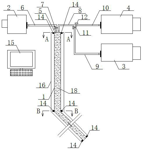
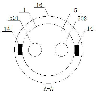
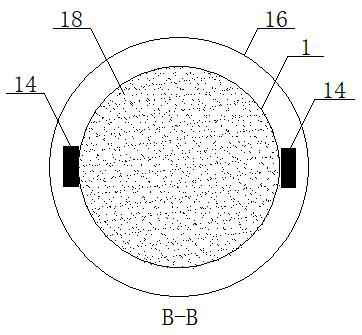
[0049] see Figure 1 to Figure 5 , a device for monitoring tower stability and filling soil holes in a karst development area, including a material pipe 1, an air supply device 2, a sand supply device 3 and a slurry supply device 4, one end of the material pipe 1 is located on the ground, and the end An end cover 5 is provided, and an air inlet 501 and a feeding hole 502 communicating with the material pipe 1 are opened on the end cover 5, and the air inlet 501 is communicated with one end of the air delivery pipe 6, and the other end of the air delivery pipe 6 is connected with the air supply pipe 6. The gas equipment 2 is connected, and the gas delivery pipe 6 is provided with a first valve 7, and the feed hole 502 is connected with one end of the feeding pipe 8, and the other end of the feeding pipe 8 is respectively connected with the sand delivery pipe 9 and the delivery pipe 9 through a three-way joint. One end of the slurry pipe 10 is connected, and the other ends of th...

Embodiment 2

[0056] Basic content is the same as embodiment 1, the difference is:

[0057] Described device also comprises controller 15, and the signal input end of described controller 15 is connected with the signal output end of monitoring equipment 14, and the signal output end of controller 15 is connected with gas supply equipment 2, sand supply equipment 3, slurry supply equipment respectively. 4. The first valve 7, the second valve 11, and the third valve 12 are connected.

Embodiment 3

[0059] Basic content is the same as embodiment 1, the difference is:

[0060]The device also includes a borehole protection tube 16, which is sleeved outside the material pipe 1, one end of the borehole protection tube 16 is located on the ground, and the other end of the borehole protection tube 16 extends to be close to the soil hole 13 The borehole protection pipe 16 is connected with the pressure tower 17, the pressure tower 17 includes a main rod 171 and a base 172, the main rod 171 is a cylindrical structure, and the base 172 is a conical structure, The base 172 is located underground, the top of the base 172 is connected to one end of the main rod 171, and the other end of the main rod 171 extends to the ground. The borehole protection pipe 16 includes a vertical cylinder 161 and an inclined cylinder 162. One end of the straight cylinder 161 is located on the ground, and the other end of the vertical cylinder 161 communicates with an end of the inclined cylinder 162 loc...


PUM


Abstract

A device for monitoring tower stability and filling soil holes in a karst development area comprises a material pipe, air supply equipment, sand supply equipment and slurry supply equipment, one end of the material pipe is located on the ground and provided with an end cover, the end cover is provided with an air inlet hole and a feeding hole which are communicated with the material pipe, the air inlet hole is communicated with the air supply equipment through an air conveying pipe, and the feeding hole is communicated with the sand supply equipment through an air conveying pipe. A first valve is arranged on the air conveying pipe, the feeding hole is communicated with one end of a sand conveying pipe and one end of a slurry conveying pipe through a material conveying pipe, the other end of the sand conveying pipe and the other end of the slurry conveying pipe are communicated with sand supply equipment and slurry supply equipment, a second valve is arranged on the sand conveying pipe, a third valve is arranged on the slurry conveying pipe, and the other end of the material pipe extends to the position close to a soil hole. Monitoring equipment is arranged on the outer surfaces of the side walls at the two ends of the material pipe and the outer surface of the side wall in the middle and is used for monitoring whether materials exist in the material pipe at the mounting position of the monitoring equipment or not. According to the design, the monitoring accuracy is improved, the construction difficulty is reduced, and the construction cost is reduced.

Description

technical field [0001] The invention relates to the field of geotechnical engineering, in particular to a device and method for monitoring the stability of towers and filling soil holes in karst development areas, and is mainly suitable for improving monitoring accuracy and reducing construction cost and construction difficulty. Background technique [0002] One-third of my country's land area is karst geology, and karst soil caves are one of the common types in karst geology, which can easily cause soil layer collapse. In recent years, due to the great demand for electricity, my country's transmission lines have developed very rapidly. The transmission line is inevitably located in the karst development area when the site is selected, and the continuous development of the soil cave has a major hidden danger to the stability of the foundation of the transmission tower. As a carrier of high-load electric energy transmission and an important lifeline project that is one of th...

Claims


Application Information

Patent Timeline
Patent Type & Authority Applications(China)
IPC IPC(8): G01D21/02
CPCG01D21/02
Inventor 周英博陈航柯方超周蠡周秋鹏段志强高晓晶陈然熊川羽王巍张赵阳马莉熊一李智威张雪霏
Owner ECONOMIC & TECH RES INST OF HUBEI ELECTRIC POWER COMPANY SGCC
Learn More