Medium strain rate tensile experiment device

An experimental device and strain rate technology, applied to measuring devices, instruments, scientific instruments, etc., can solve the problems of difficult to maintain a stable strain rate, doubtful effect, difficult to accurately analyze and control the strain rate of the sample, and achieve accurate and stable control of strain The effect of smooth rate and strain rate and simple structure

Pending Publication Date: 2022-03-08
GUANGZHOU GRG METROLOGY & TEST CO LTD +1
View PDF7 Cites 0 Cited by
  • Summary
  • Abstract
  • Description
  • Claims
  • Application Information

AI Technical Summary

Problems solved by technology

[0006] (1) The driving source of the impact output is mostly electric drive or indirect electric drive. The test principle is consistent with the Hopkinson rod, and the strain rate is difficult to maintain stability.
[0007] (2) There are too many connectors between the shock source and the sample, the shock wave is transmitted to the sample after passing through multiple connectors, and the strain rate of the sample is difficult to accurately analyze and control
[0008] (3) There is a lack of a quantitative control method for the strain rate, and whether a stable strain rate control can be achieved in the prior art is questionable.
[0009] Therefore, in the prior art, due to the delay of the impact response during the tensile test, the constant strain rate cannot be guaranteed, so that the stress-strain curve obtained in the experiment cannot represent the mechanical properties of the material at a stable strain rate.

Method used


Image

  • Medium strain rate tensile experiment device
  • Medium strain rate tensile experiment device
  • Medium strain rate tensile experiment device

Examples


Embodiment 1

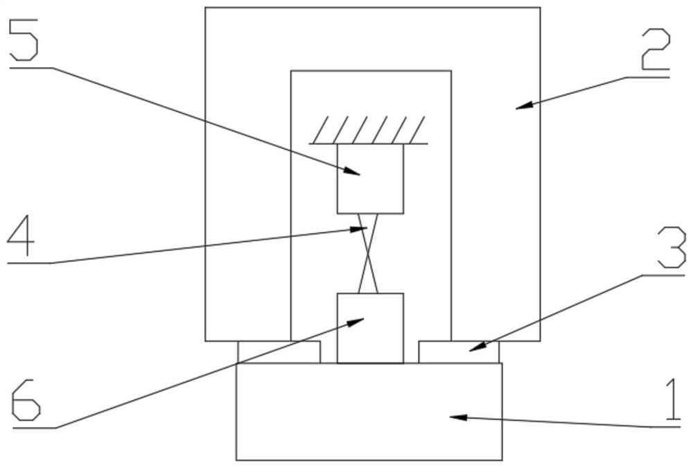
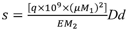
[0043] The upper clamp 5 is fixedly arranged on the tensile testing machine, and the sample 4 is arranged between the upper clamp 5 and the lower clamp 6; the base 1 is connected with the lower clamp 6, and the base 1 The drop hammer 2 is arranged above; the upper surface of the base 1 is provided with a buffer pad 3 corresponding to the drop hammer 2; the buffer pad 3 is an annular pad, and the drop hammer 2 is an annular drop hammer. The lower surface of the lower clamp 6 is fixedly connected, and the physical parameters of the buffer pad 3 are designed through the following formula:

[0044]

[0045] Wherein, s is the effective contact area between the drop weight 2 and the buffer pad 3, M 1 is the mass of drop hammer 2, E is the modulus of elasticity of buffer pad 3, M 2 is the quality of the base 1, D is the damping of the cushion 3, d is the thickness of the cushion 3, and q is a constant calibrated according to the experimental conditions.


PUM


Abstract

The invention relates to the technical field of dynamic mechanical property testing of materials, in particular to a medium-strain-rate tensile experiment device. Comprising a drop hammer, a base, a sample clamp and a sample, the sample clamp comprises an upper clamp and a lower clamp, the upper clamp is fixedly arranged, and the sample is arranged between the upper clamp and the lower clamp; the base is connected with the lower clamp, and the drop hammer is arranged above the base; and a buffer pad corresponding to the drop hammer is arranged on the upper surface of the base. The physical parameters of the buffer pad are designed, and the device is extremely simple in structure and convenient to operate; the strain rate can be quickly stable; and the strain rate can be accurately controlled, a corresponding relation is established between the physical parameters of the cushion pad, the base mass and the drop hammer mass, and the strain rate can be accurately and stably controlled by selecting the cushion pad with proper physical parameters.

Description

technical field [0001] The invention relates to the technical field of material dynamic mechanical performance testing, in particular to a medium strain rate tensile test device. Background technique [0002] Strain rate is an important parameter for the mechanical properties of materials. Usually, the strain rate distribution of materials is wide, which brings challenges to the study of material strain rates. At present, most of the researchers' studies on the strain rate of materials focus on the low strain rate range (1s -1 below) and high strain rate range (100s -1 above), centering strain rate (1s -1 ~100s -1 ) are relatively scarce. In practical engineering applications, it is very important to understand the stress-strain behavior of a material at a medium strain rate, and a large number of experiments have shown that when the material is from a low strain rate to a high strain rate, the medium strain rate is in the middle of the mechanical properties of the mate...

Claims


Application Information

Patent Timeline
Patent Type & Authority Applications(China)
IPC IPC(8): G01N3/08G01N3/303G01N3/04G01N3/02
CPCG01N3/08G01N3/303G01N3/04G01N3/02G01N2203/0017G01N2203/0039
Inventor 熊铃华刘伟赵可沦明志茂
Owner GUANGZHOU GRG METROLOGY & TEST CO LTD
Why Eureka
Try Eureka