
Equipment data acquisition analyzer

A device data and parser technology, applied in the parser field, can solve the problems of inconvenience to carry and move, low practicability, poor heat dissipation, etc., and achieve the effect of accelerating the cooling effect, good heat dissipation effect, and preventing dust clogging.

Pending Publication Date: 2022-03-08
苏州微缔软件股份有限公司
View PDF0 Cites 0 Cited by
  • Summary
  • Abstract
  • Description
  • Claims
  • Application Information

AI Technical Summary

Problems solved by technology

[0002] The data acquisition equipment used in the traditional industrial field, such as PLC, data acquisition module, etc., passes the data collected on site through the data acquisition analyzer, a special device for data analysis, which has data acquisition, data processing, data storage and data transmission, etc. Function, when the device data collection analyzer is performing data analysis, the internal components will generate heat, and the heat will be dust-proof and heat-dissipated through the dust-proof net. However, after a long period of use, the dust-proof net in the current equipment data collection The mesh holes of the grid will be blocked by some dust, resulting in poor heat dissipation, and the existing equipment data acquisition analyzer is usually fixedly installed on a device, which is inconvenient to carry and move, making the practicability not high

Method used


Image

  • Equipment data acquisition analyzer
  • Equipment data acquisition analyzer
  • Equipment data acquisition analyzer

Examples


Embodiment Construction

[0022] In order to enable those skilled in the art to better understand the present invention, the technical solution of the present invention will be further described below in conjunction with the accompanying drawings and embodiments.

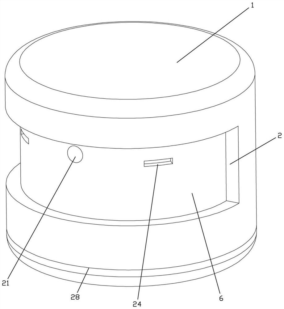
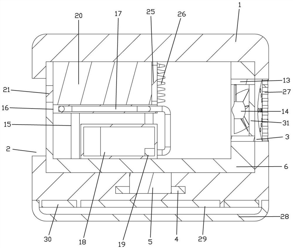
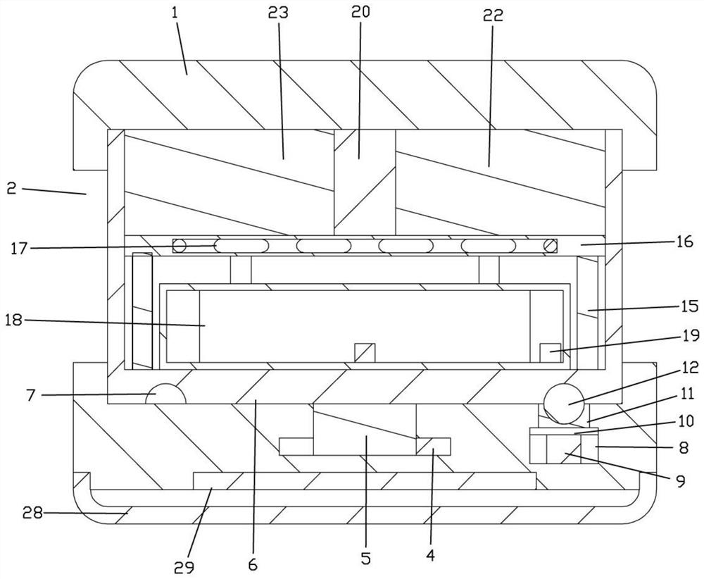
[0023] like Figure 1-4 As shown, in the equipment data acquisition analyzer of the present invention, the protective shell 1 is arranged in a cylindrical structure, the adjustment groove 2 is provided on one side of the protective shell 1, the heat dissipation groove 3 is provided on the other side of the protective shell 1, and the inner bottom of the protective shell 1 A bearing seat 4 is installed, the bearing seat 4 is connected with a rotating shaft 5, the rotating shaft 5 is connected with an adjusting sleeve 6, and positioning holes 7 are provided on both sides of the bottom of the adjusting sleeve 6, and the protective shell 1 is provided with a positioning cavity 8 on the side corresponding to the positioning hole 7 , a positioning...


PUM


Abstract

The invention discloses an equipment data acquisition analyzer which comprises a protective shell, an adjusting groove is formed in one side of the protective shell, a heat dissipation groove is formed in the other side of the protective shell, a bearing seat is installed at the bottom of the inner side of the protective shell, the bearing seat is connected with a rotating shaft, the rotating shaft is connected with an adjusting sleeve, a through groove is formed in the side, corresponding to the heat dissipation groove, of the adjusting sleeve, and a heat dissipation sleeve is installed in the through groove. A dustproof net is installed on one side of the heat dissipation sleeve, a heat dissipation fan is installed in the heat dissipation sleeve, a supporting column is installed on the adjusting sleeve and connected with a partition plate, the partition plate is provided with a cooling groove, a water cooling pipe is installed in the cooling groove, the input end of the water cooling pipe is connected with a cooling box, the cooling box is provided with a miniature water pump, and the miniature water pump is connected with the input end of the water cooling pipe. The other side of the cooling box is connected with the output end of the water cooling pipe, the partition plate is provided with a storage battery, the storage battery is electrically connected with a charging jack, the charging jack is formed in the adjusting sleeve, the storage battery is electrically connected with a data acquisition module and an analysis module, and the data acquisition module and the analysis module are both connected with insertion ports.

Description

technical field [0001] The invention belongs to the technical field of parsers, and in particular relates to a device data collection parser. Background technique [0002] The data acquisition equipment used in the traditional industrial field, such as PLC, data acquisition module, etc., passes the data collected on site through the data acquisition analyzer, a special device for data analysis, which has data acquisition, data processing, data storage and data transmission, etc. Function, when the device data collection analyzer is performing data analysis, the internal components will generate heat, and the heat will be dust-proof and heat-dissipated through the dust-proof net. However, after a long period of use, the dust-proof net in the current equipment data collection The mesh holes of the grid will be blocked by some dust, resulting in poor heat dissipation, and the existing equipment data collection analyzer is usually fixedly installed on a device, which is inconven...

Claims


Application Information

Patent Timeline
Patent Type & Authority Applications(China)
IPC IPC(8): H05K7/20H05K7/14H05K5/02
CPCH05K7/20181H05K7/20318H05K7/14H05K5/0213H05K5/0204
Inventor 郑立新
Owner 苏州微缔软件股份有限公司
Learn More