Flotation device for mining flotation process
A flotation device and flotation technology are applied in the field of flotation technology, which can solve problems such as poor flotation effect, and achieve the effects of high work efficiency, improved adsorption rate, and improved ore flotation rate.
- Summary
- Abstract
- Description
- Claims
- Application Information
AI Technical Summary
Problems solved by technology
Method used
Image
Examples
Embodiment 1
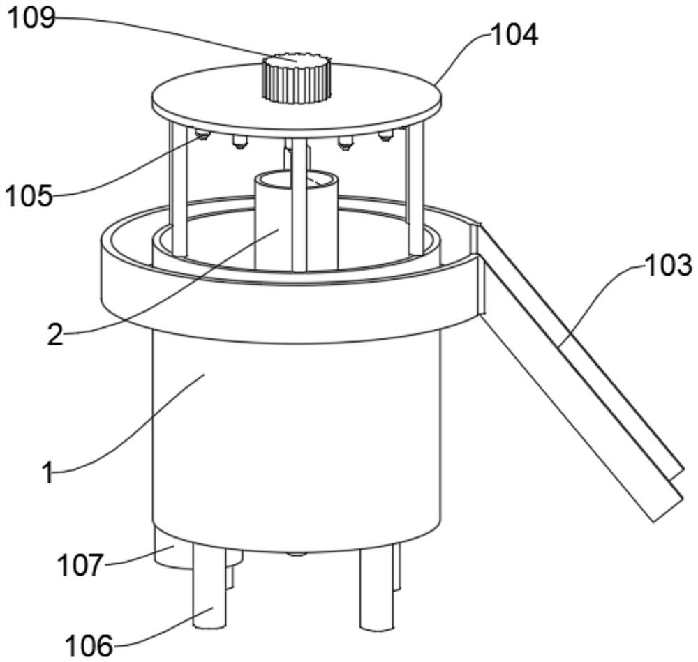
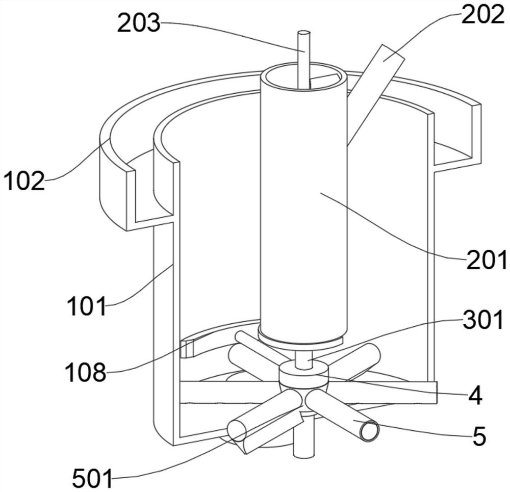
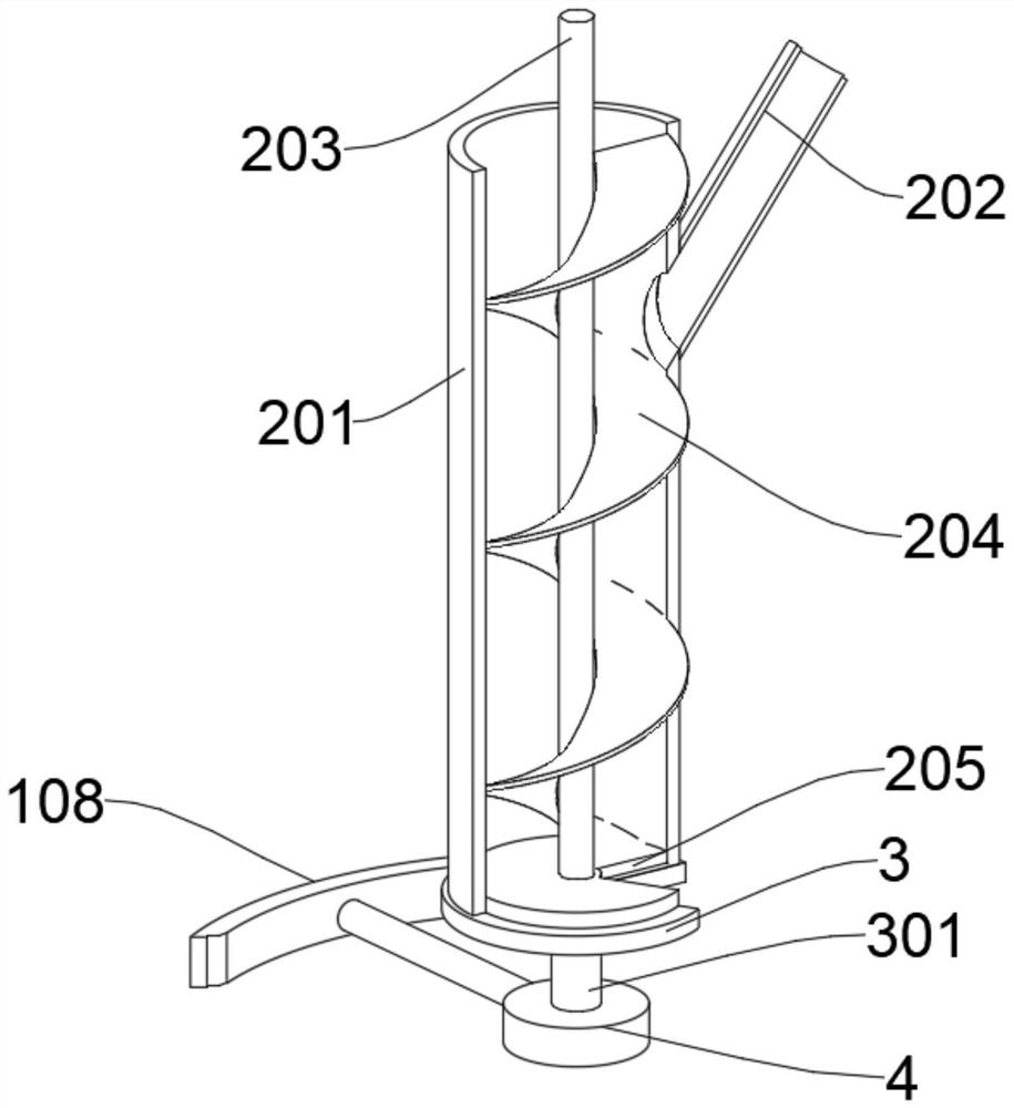
[0035] Please refer to Figures 1, 2, 3, and 5, a flotation device for mining flotation technology, including a flotation machine main body 1, which includes a flotation cell 101, and the inner center of the flotation cell 101 is fixed The feeding cylinder 2 is connected, and the feeding cylinder 2 includes a cylinder body 201, the middle part of the cylinder body 201 is rotated and provided with a rotating shaft 203, the bottom of the cylinder body 201 is provided with a fan-shaped outlet 205, and the bottom of the cylinder body 201 is fitted and rotated and connected with a rotary gate 3. The rotary gate 3 is provided with a gap corresponding to the shape of the fan-shaped outlet 205. The bottom of the rotary gate 3 is fixedly connected with a sleeve 301. The sleeve 301 is sleeved on the outside of the rotating shaft 203. The bottom of the rotating shaft 203 is connected with a timing control device 4 , The bottom of the timing control device 4 is connected with an air intake ...
Embodiment 2
[0045] Please refer to Figures 6-7, the difference in the basis of Embodiment 1 is that the air rod 502 is used to make air bubbles, and the inside of the air rod 502 is a hollow structure with openings at both ends, and the bottom of the air rod 502 is equidistant A number of air outlets A509 are opened, and the air pressure balance device 6 is installed inside the air rod 502 , and the air pressure balance device 6 is in frictional contact with the inner wall of the air rod 502 .
[0046] The air pressure balance device 6 includes a balance bar 601. The inside of the balance bar 601 is hollow and one end opening near the air chamber 501 is open. The bottom of the balance bar 601 is provided with several air outlet holes B602, and the distance between the air outlet holes B602 and the distance between the air outlet holes A509 is equal. One end of the rod 601 close to the air chamber 501 is connected to the head spring B603, and the end of the air rod 502 close to the air cham...
Embodiment 3
[0051] Please refer to Figure 4, the difference in the basis of the combined embodiments 1 and 2 is that,
[0052] A flotation device for mine flotation process, comprising a flotation machine main body 1, the flotation machine main body 1 includes a flotation cylinder 101, the inner center of the flotation cylinder 101 is fixedly connected with a feed cylinder 2, and the feed cylinder 2 Including the cylinder 201, the middle part of the cylinder 201 is rotated with a rotating shaft 203, the bottom of the cylinder 201 is provided with a fan-shaped outlet 205, the bottom of the cylinder 201 is fitted and rotated connected with a rotary gate 3, and the rotary gate 3 is provided with a fan-shaped outlet The gap corresponding to the shape of 205, the bottom of the rotary gate 3 is fixedly connected with the sleeve 301, the sleeve 301 is sleeved on the outside of the rotating shaft 203, the bottom of the rotating shaft 203 is connected with the timing control device 4, and the botto...
PUM
 Abstract
Description
Claims
Application Information
 - R&D
- Intellectual Property
- Life Sciences
- Materials
- Tech Scout
- Unparalleled Data Quality
- Higher Quality Content
- 60% Fewer Hallucinations
Browse by: Latest US Patents, China's latest patents, Technical Efficacy Thesaurus, Application Domain, Technology Topic, Popular Technical Reports.
© 2025 PatSnap. All rights reserved.Legal|Privacy policy|Modern Slavery Act Transparency Statement|Sitemap|About US| Contact US: help@patsnap.com


