Hand-held laser welding head with adjustable light spots

A laser welding head and light spot technology, which is applied in laser welding equipment, welding equipment, metal processing equipment, etc., can solve the problems of difficult to accurately adjust the size of the light spot, loss of energy, high cost, etc., and achieve the effect of adjusting the size of the light spot and convenient calculation

Pending Publication Date: 2022-03-11
武汉奥森迪科智能科技股份有限公司
View PDF0 Cites 1 Cited by
  • Summary
  • Abstract
  • Description
  • Claims
  • Application Information

AI Technical Summary

Problems solved by technology

[0004] Some solutions have also been pre-researched. For example, the dual vibrating mirror fits a circle under the control of the circuit, which is costly; the rotating mirror forms an elliptical spot after focusing, which does not meet the requirements; the light is refracted by combining lenses out of the angle, and then rotate the combined lens to form a circular spot. First, it is difficult to accurately adjust the size of the spot. It needs to be adjusted and measured to obtain the required diameter of the spot. Second, the incident light is not perpendicular to the plane of the focusing lens. Small angle, refraction will also lose part of the energy

Method used


Image

  • Hand-held laser welding head with adjustable light spots
  • Hand-held laser welding head with adjustable light spots
  • Hand-held laser welding head with adjustable light spots

Examples


Embodiment Construction

[0035] Next, the technical scheme in the embodiment of the present invention will be described in conjunction with the embodiment of the present invention, and is clearly, and it is clear that the described embodiments are merely the embodiments of the present invention, not all of the embodiments. Based on the embodiments in the present invention, all other embodiments obtained by those of ordinary skill in the art are in the range of the present invention without making creative labor.

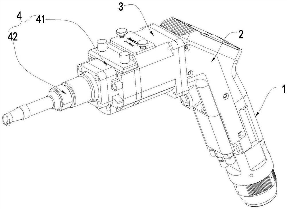
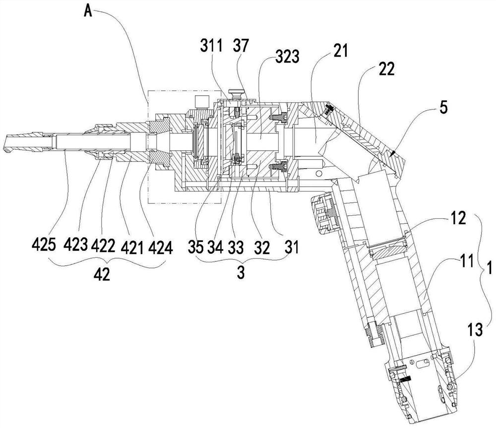
[0036] Such as figure 1 As shown, combined figure 2 The present invention provides a hand-held laser welding head that can be adjusted by a spot, which includes a sequentially connected collimator assembly 1, a reflective assembly 2, a regulating assembly 3, and an aliasing assembly 1, a reflective assembly 2, and an adjustment assembly. 3 The optical path channels with each other are provided for laser passing. The laser is collected by the collimating assembly 1 after the reflective assembly 2...


PUM

PropertyMeasurementUnit
diameteraaaaaaaaaa

Abstract

The handheld laser welding head comprises a collimation assembly, a reflection assembly, an adjusting assembly and an emitting assembly which are connected in sequence, the adjusting assembly comprises a shell, a holder motor, an adapter disc, a mirror box and a focusing mirror, the holder motor, the adapter disc, the mirror box and the focusing mirror are arranged in the shell, a light through hole is formed in the center of the holder motor, and the holder motor comprises a stator and a rotor; one end of the switching disc is coaxially and fixedly connected with the rotor, a through hole is eccentrically formed in the switching disc, the distance from the center axis of the through hole to the center axis of the light through hole is a first preset value, the lens box is rotationally arranged at the other end of the switching disc, a through groove is eccentrically formed in the lens box, and the focus lens is coaxially and fixedly arranged in the through groove. The distance between the center axis of the through groove and the center axis of the through hole is a second preset value, the second preset value is smaller than or equal to the first preset value, and the mirror box is rotated around the center of the through hole in the transfer disc by rotating the mirror box, so that the relative position of the focus lens is adjustable, the emergent laser rotates with the center of the rotor as the center axis, and an adjustable circular light spot is formed.

Description

Technical field [0001] The present invention relates to the field of laser welding joints, and more particularly to a spot-operated laser welding joint. Background technique [0002] The laser welded adapter is a device that is welded by the energy of the laser beam. By connecting the laser, the input high energy laser light, the laser welded joint is focused by lens, forming high-energy density, and then welds the surgical workpiece. [0003] A wide variety of hand-held laser welding joints have emerged, and the first-generation welded joint is to use the fixed spot point to welding, and there is a variety of light spot, difficult to align the weld, and the energy is too concentrated. The second generation welding joint has a straight line, circular, triangular and other forms of spot, wherein the circular spot application is relatively wide, so how to form a circular spot, the circular diameter is adjusted, how to achieve the center of the spot and the light spot center R & D c...

Claims


Application Information

Patent Timeline
Patent Type & Authority Applications(China)
IPC IPC(8): B23K26/00B23K26/046B23K26/06B23K26/064B23K26/073B23K26/142B23K26/70
CPCB23K26/0096B23K26/046B23K26/142B23K26/064B23K26/0643B23K26/702B23K26/073
Inventor 傅法煜谢端
Owner 武汉奥森迪科智能科技股份有限公司
Why Eureka
Try Eureka