
Offset beam occultation GNSS antenna

An antenna and beam technology, applied in the field of space detection instruments, can solve the problems of increasing the envelope of the whole star, increasing the weight of the whole star, poor environmental adaptability, etc., and achieve the effect of reducing the weight of the star, good environmental adaptability and low cost

Pending Publication Date: 2022-03-11
浙江时空道宇科技有限公司 +1
View PDF0 Cites 0 Cited by
  • Summary
  • Abstract
  • Description
  • Claims
  • Application Information

AI Technical Summary

Problems solved by technology

The method of phase-shifting the T / R components at the rear end of the antenna has poor environmental adaptability and high cost; erecting a bracket on the star will increase the weight of the whole star and increase the envelope of the whole star

Method used


Image

  • Offset beam occultation GNSS antenna
  • Offset beam occultation GNSS antenna

Examples


Embodiment Construction

[0020] The specific implementation manners of the present invention will be further described in detail below in conjunction with the accompanying drawings and embodiments. The following examples are used to illustrate the present invention, but are not intended to limit the scope of the present invention.

[0021] In the description of the present invention, it should be noted that the orientation or positional relationship indicated in this description is based on the orientation or positional relationship shown in the drawings, and is only for the convenience of describing the present invention and simplifying the description, rather than indicating or implying the It should not be construed as limiting the invention that a device or element must have a particular orientation, be constructed, and operate in a particular orientation.

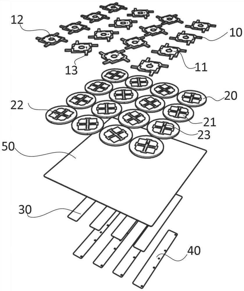
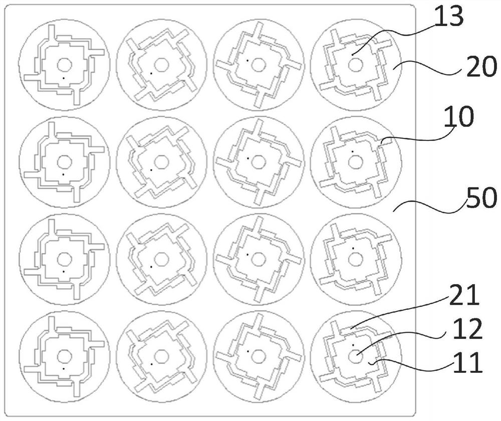
[0022] Please refer to Figure 1-2 A kind of partial beam occultation GNSS antenna provided by the present invention includes a plurality of...


PUM


Abstract

A bias beam occultation GNSS antenna disclosed by the present invention comprises an antenna unit, the antenna unit comprises a first layer dielectric plate, a second layer dielectric plate, a third layer dielectric plate, a fourth layer dielectric plate and a metal base plate, the first layer dielectric plate is printed with a first microstrip patch, the first layer dielectric plate is provided with a plated-through hole, and the second layer dielectric plate is printed with a second microstrip patch. A first microstrip patch is printed on the first dielectric plate, a second microstrip patch is printed on the second dielectric plate, a gap is formed in the second microstrip patch, a feed network is arranged on the third dielectric plate, and the fourth dielectric plate and the third dielectric plate are attached to form a strip line feed network. The first-layer dielectric plate, the second-layer dielectric plate, the metal bottom plate, the third-layer dielectric plate and the fourth-layer dielectric plate are sequentially stacked from top to bottom, the first-layer dielectric plate and the second-layer dielectric plate are arranged in an array mode, and each column of the first-layer dielectric plate and the second-layer dielectric plate are rotationally arranged at a fixed angle difference. According to the invention, antenna beam deflection is realized through a space phase shift method of rotating an array element angle. The cost is low and the environmental adaptability is good.

Description

technical field [0001] The invention relates to the field of space detection instruments, in particular to a partial-beam occultation GNSS (Global Navigation Satellite System, Global Navigation Satellite System) antenna. Background technique [0002] When the GNSS signal passes through the ionosphere and atmosphere and reaches the low-orbit satellite at the other end, due to the existence of the propagation medium and its gradient, additional time delay and bending will be generated. Using these additional time delay and bending information, based on certain assumptions Under certain conditions, the electron density of the ionosphere and the refractive index, temperature, density, and water vapor content of the lower atmosphere can be obtained by inversion. As an essential part of the spaceborne occultation detection system, the performance of the antenna directly affects the performance of the entire system. The atmospheric occultation antenna usually used for GNSS radio o...

Claims


Application Information

Patent Timeline
IPC IPC(8): H01Q1/38H01Q1/50H01Q1/28H01Q3/30H01Q21/06
CPCH01Q1/38H01Q1/50H01Q1/288H01Q21/065H01Q3/30
Inventor 万睿丁晟杨冰
Owner 浙江时空道宇科技有限公司
Learn More