Waste recovery device for stainless steel shot production

A technology of scrap recycling and stainless steel, applied in the field of scrap recycling devices for stainless steel shot production, can solve the problems of steel shot quality, large explosion range, inconvenient centralized recycling, etc., and achieve the effect of preventing unqualified quality and accelerating recycling speed.

Active Publication Date: 2022-03-15
无锡锋速钢丸有限公司
View PDF14 Cites 2 Cited by
  • Summary
  • Abstract
  • Description
  • Claims
  • Application Information

AI Technical Summary

Problems solved by technology

[0004] In the above technical solution, it is proposed to collect the powdered metal dust through the dust collection system. It can be seen from the figure that it is only installed at the bottom of the equipment. However, when the molten metal is atomized into metal powder, it will explode to the surroundings. The range is large, and it is not convenient for subsequent centralized recovery only through the dust collection system. At the same time, some dust may contact the formed steel shot and be welded on its surface, thus causing quality problems of the steel shot; therefore, the present invention provides a Waste recycling device for production of stainless steel shot

Method used


Image

  • Waste recovery device for stainless steel shot production
  • Waste recovery device for stainless steel shot production
  • Waste recovery device for stainless steel shot production

Examples


Embodiment 1

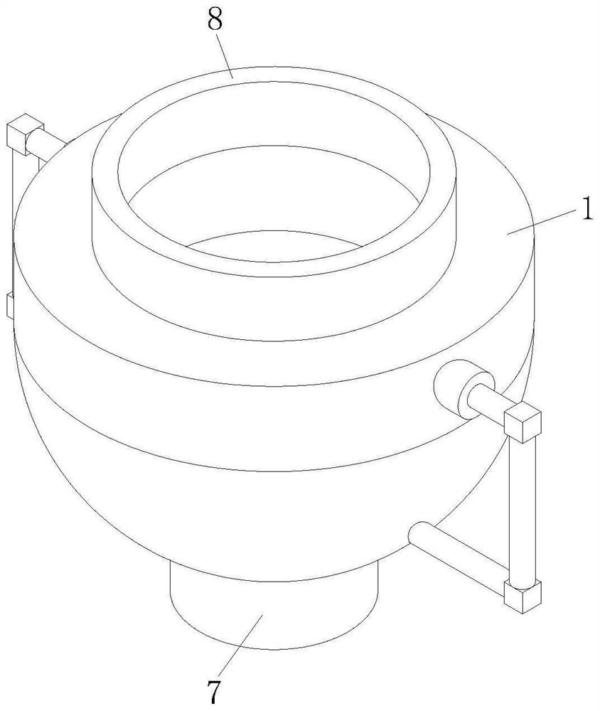
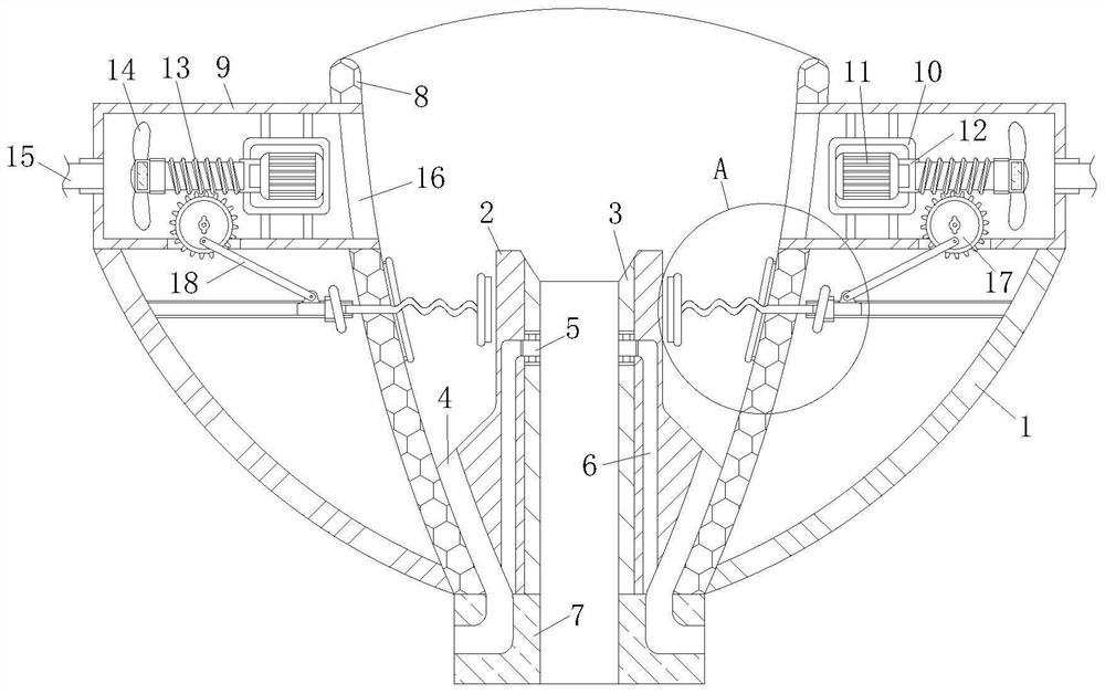
[0028] like Figure 1 to Figure 2As shown, a waste recycling device for stainless steel shot production according to the embodiment of the present invention includes a protective shell 1, a receiving plate 8 is fixed inside the protective shell 1, and a guide plate 2 is fixed inside the receiving plate 8 , the inside of the guide plate 2 is fixed with a blanking tube 3, the recovery tube 4 is fixed between the guide plate 2 and the receiving plate 8, the bottom end of the protective shell 1 is fixed with a mounting frame 7, and the mounting frame 7 There is a recovery hole connected to the recovery pipe 4 inside, and a suction shell 9 is fixed on the top of the protective shell 1, and the suction shell 9 is connected through the receiving plate 8, and the suction shell 9 is internally set There is a servo drive assembly 11, a shaft coupling 12 is installed on the side of the servo drive assembly 11 away from the receiving plate 8, a worm 13 is fixed inside the coupling 12, and...

Embodiment 2

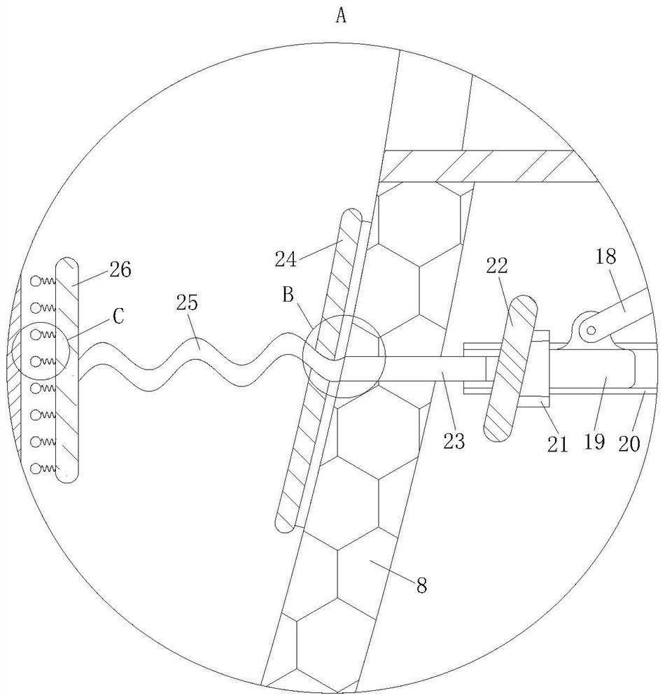
[0038] like Figure 5 As shown in Comparative Example 1, another embodiment of the present invention is: the side of the knocking plate 26 away from the bent rod 25 is fixed with multiple groups of vibrating springs 27, and the vibrating springs 27 are far away from the knocking plate 26 One side of each is fixed with a knocking ball 28; during work, when the knocking plate 26 hits the guide plate 2, it will first drive the knocking ball 28 to hit the guide plate 2, and then vibrate the spring under the effect of the impact force 27 bends, thereby driving the knocking ball 28 to vibrate, and the knocking ball 28 will scratch the surface of the guide plate 2 during the vibration process, thereby cleaning the surface of the guide plate 2, and at the same time, the knocking plate 26 and the guide plate After the plate 2 is separated, under the action of the elastic force of the vibrating spring 27, a part of the percussion ball 28 will still collide with the guide plate 2, thereb...


PUM


Abstract

The invention belongs to the technical field of stainless steel shot production equipment, and particularly relates to a waste recovery device for stainless steel shot production, which comprises a protective shell, a bearing plate is fixed in the protective shell, a guide plate is fixed in the bearing plate, and a blanking pipe is fixed in the guide plate. A recycling pipe is fixed between the guide plate and the bearing plate, a mounting frame is fixed to the bottom end of the protective shell, a recycling hole connected with the recycling pipe is formed in the mounting frame, and a back suction shell is fixed to the top of the protective shell. Equipment is installed between atomization equipment and cooling equipment, so that molten metal cannot be splashed when atomized and exploded into powder, the scattered powder is pulled through negative pressure, the effect of centralized recovery of waste is achieved, meanwhile, rising airflow is discharged in a discharging pipe, the powder cannot fall off from the discharging pipe, and the powder is prevented from falling off from the discharging pipe. Therefore, unqualified quality caused by the fact that the surfaces of the finished steel shots are contaminated with powder is effectively prevented.

Description

technical field [0001] The invention belongs to the technical field of stainless steel shot production equipment, in particular to a waste recycling device for stainless steel shot production. Background technique [0002] Steel shot is a very common material, which has many uses in the process of machining, and there are two common ways to manufacture steel shot, one is by cutting and throwing round, and the other is by air Atomization and gas atomization have the characteristics of high production efficiency and high yield. The stainless steel shot produced has significant advantages such as rounded pellets, uniform size, moderate hardness, strong impact, wide coverage, and long service life. The gas pressure during atomization is also an important factor. If the gas pressure is too high, the molten metal will be atomized into powder. [0003] A Chinese patent with the publication number CN208528092U discloses a stainless steel pellet atomization device, including a melti...

Claims


Application Information

Patent Timeline
Patent Type & Authority Applications(China)
IPC IPC(8): B22F9/08
CPCB22F9/082B22F2009/0896Y02P70/10
Inventor 王霆俞瑶希
Owner 无锡锋速钢丸有限公司
Why Eureka
Try Eureka