Eureka AIR delivers breakthrough ideas for toughest innovation challenges, trusted by R&D personnel around the world.

Suspension support three-face numerical control milling machine

A technology for CNC milling machines and suspension brackets, applied to milling machine equipment, milling machine equipment details, supports, etc., can solve problems affecting the machining accuracy of suspension brackets, affecting the positioning accuracy of suspension brackets, increasing labor intensity of workers, etc., to ensure production beats, reduce The effect of cleaning difficulty and reducing clamping difficulty

Pending Publication Date: 2022-03-15
YANCHENG BAOLILAI PRECISION MACHINERY MFG
View PDF0 Cites 1 Cited by
  • Summary
  • Abstract
  • Description
  • Claims
  • Application Information

AI Technical Summary

Problems solved by technology

[0003] The suspension bracket is an indispensable and important part of the suspension system. The structure of the suspension bracket is irregular and special-shaped parts, and there are 3 special-shaped surfaces that need to be processed. The existing processing method is: first process one surface of the suspension bracket, Then adjust the surface of the suspension bracket, perform secondary processing, and repeatedly disassemble and assemble until all three surfaces are processed. This kind of processing method not only affects the positioning accuracy of the suspension bracket, but also increases the labor intensity of the workers, and will also affect the quality of the suspension bracket. Machining accuracy and low efficiency of processing methods have greatly affected the production capacity of the enterprise, the competitiveness of the enterprise is limited, and the production cost is high. Technical personnel in the field need to solve this technical problem urgently

Method used


Image

  • Suspension support three-face numerical control milling machine
  • Suspension support three-face numerical control milling machine
  • Suspension support three-face numerical control milling machine

Examples


Embodiment Construction

[0028] The following will clearly and completely describe the technical solutions in the embodiments of the present invention with reference to the accompanying drawings in the embodiments of the present invention. Obviously, the described embodiments are only some, not all, embodiments of the present invention. Based on the embodiments of the present invention, all other embodiments obtained by persons of ordinary skill in the art without making creative efforts belong to the protection scope of the present invention.

[0029] In the description of the present invention, it should be noted that the terms "center", "upper", "lower", "left", "right", "vertical", "horizontal", "inner", "outer" etc. The indicated orientation or positional relationship is based on the orientation or positional relationship shown in the drawings, and is only for the convenience of describing the present invention and simplifying the description, rather than indicating or implying that the referred d...


PUM


Abstract

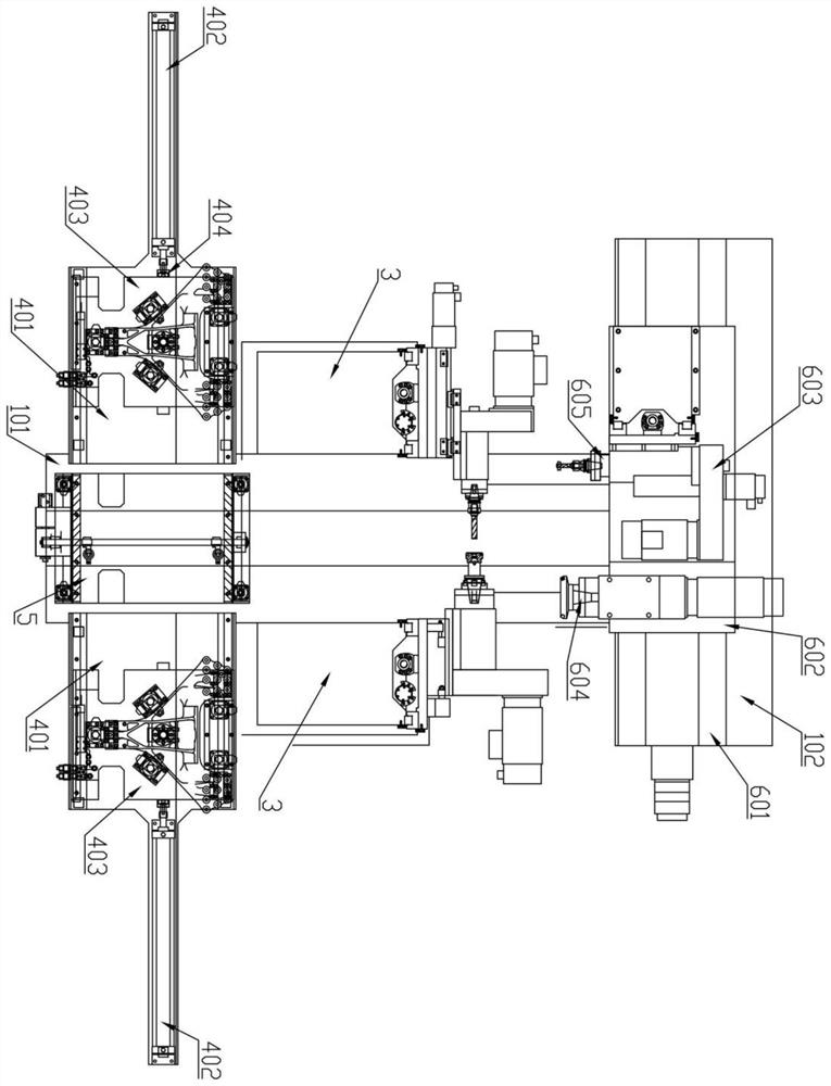
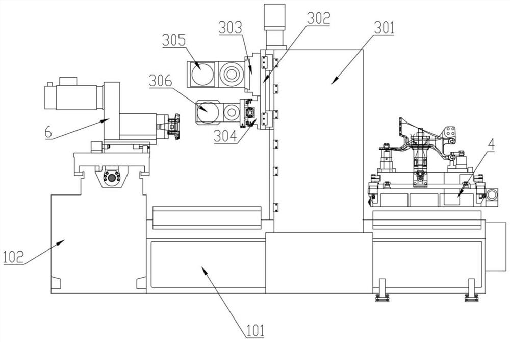
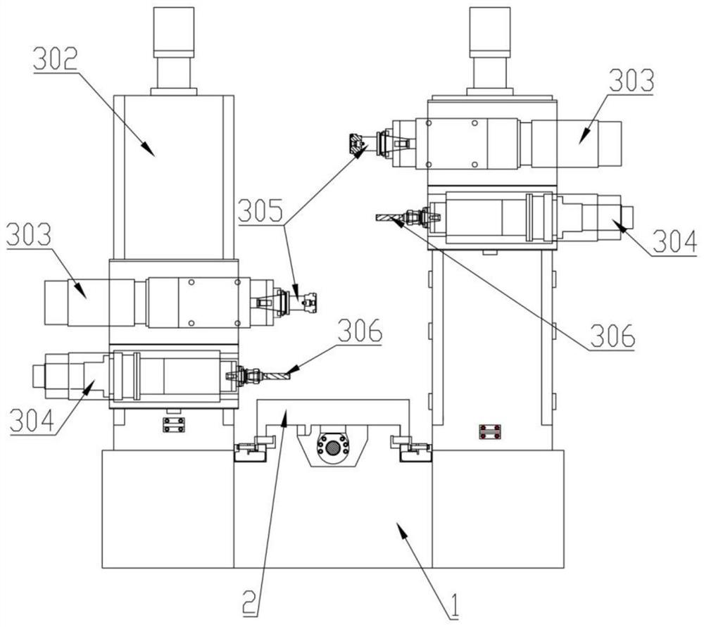
The invention relates to a suspension support three-face numerical control milling machine which comprises a composite base, the composite base is provided with a first base and a second base, the first base is provided with a middle servo sliding table, and vertical machining devices and feeding bins are symmetrically arranged on the two sides of the middle servo sliding table. The vertical machining device is located between the feeding bin and the second base, the middle servo sliding table is connected with a conveying bottom plate, the second base is provided with a horizontal machining device, the horizontal machining device is provided with a transverse servo sliding table, and a Y-direction hydraulic sliding table and a cross-shaped servo sliding table are arranged on the transverse servo sliding table in parallel. The Y-direction hydraulic sliding table is connected with an end face milling power head, the cross-shaped servo sliding table is connected with a drilling power head, and the end face milling power head and the drilling power head face the vertical machining device. Multi-station simultaneous machining is adopted, the product clamping frequency is reduced, and the machining precision is improved.

Description

technical field [0001] The invention belongs to the technical field of mechanical processing, and in particular relates to a three-sided numerical control milling machine for a suspension bracket. Background technique [0002] At present, with the development of society, automobiles have become the main means of transportation for human beings, bringing convenience to people's travel. The automobile suspension system refers to the entire support system composed of springs and shock absorbers between the vehicle body and tires. The function of the suspension system is to support the body and improve the riding experience. Different suspension settings will give the driver different driving experiences. The seemingly simple suspension system integrates various forces and determines the stability, comfort and safety of the car. It is one of the most critical components of modern cars. [0003] The suspension bracket is an indispensable and important part of the suspension syst...

Claims


Application Information

Patent Timeline
Patent Type & Authority Applications(China)
IPC IPC(8): B23C3/00B23P23/02B23Q1/25B23Q3/08B23Q7/00
CPCB23C3/00B23P23/02B23Q3/082B23Q7/00B23Q1/25
Inventor 顾金祥沈宏宁沈龙海
Owner YANCHENG BAOLILAI PRECISION MACHINERY MFG
Why Eureka
Eureka Blog
Learn More