Concrete building surface defect repairing device and repairing method thereof

A defect repair, body surface technology, applied in building maintenance, construction, building construction, etc., can solve problems such as low repair efficiency, inability to realize automatic processing, and repair operation danger, etc., to improve efficiency, improve repair efficiency, reduce dangerous effect

Pending Publication Date: 2022-03-15
安徽联赢环境建设有限公司
View PDF7 Cites 0 Cited by
  • Summary
  • Abstract
  • Description
  • Claims
  • Application Information

AI Technical Summary

Problems solved by technology

[0004] The invention proposes a device for repairing surface defects of concrete buildings and its repairing method, which solves the problem that existing repair operations

Method used


Image

  • Concrete building surface defect repairing device and repairing method thereof
  • Concrete building surface defect repairing device and repairing method thereof
  • Concrete building surface defect repairing device and repairing method thereof

Examples


Embodiment 1

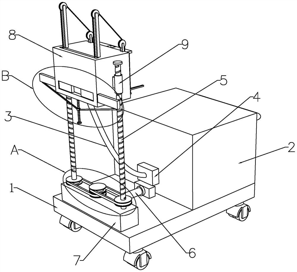
[0038] refer to figure 1 , a device for repairing surface defects of concrete buildings, including a mobile car body 1, a raw material box 2 is fixedly installed on one side of the top end of the mobile car body 1, and a raw material box 2 is fixedly installed on the other side facing the mobile car body 1 The first electric telescopic rod 6 , the end of the first electric telescopic rod 6 is fixedly connected with the movable base 7 , and the movable base 7 is slidably installed on the top end of the mobile vehicle body 1 .

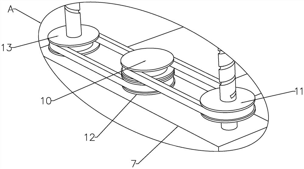
[0039] refer to figure 1 and figure 2, both sides of the top of the movable base 7 are rotatably equipped with a lifting screw 5, and a driving mechanism is arranged between the movable base 7 and the lifting screw 5, and the driving mechanism includes a driving motor, a first main pulley 10, a first secondary pulley 11, a Two primary pulleys 12 and the second secondary pulley 13, the inside of the movable base 7 is fixedly installed with a drive moto...

Embodiment 2

[0046] refer to Figure 8 , the top of the repair box 8 is provided with a limit groove, and the inner wall of the repair box 8 near the discharge port 14 is slidably equipped with a baffle plate 32, and the limit groove matches the baffle plate 32, and the top of the baffle plate 32 is aligned with the first movable plate. Two traction wire ropes 27 that are symmetrically distributed are connected between the tops of 19, and the top of the repair box 8 is provided with a guiding mechanism that cooperates with the traction wire ropes 27.

[0047] refer to Figure 6 and Figure 8 , the guide mechanism includes a first mounting frame 29, a first guide wheel 28, a second mounting frame 31 and a second guiding wheel 30, and the top of the repair box 8 is fixedly equipped with two groups of first mounting frames 29 and two groups of symmetrically distributed The second installation frame 31 that is symmetrically distributed, and the first guide wheel 28 is installed on the top of...

Embodiment 3

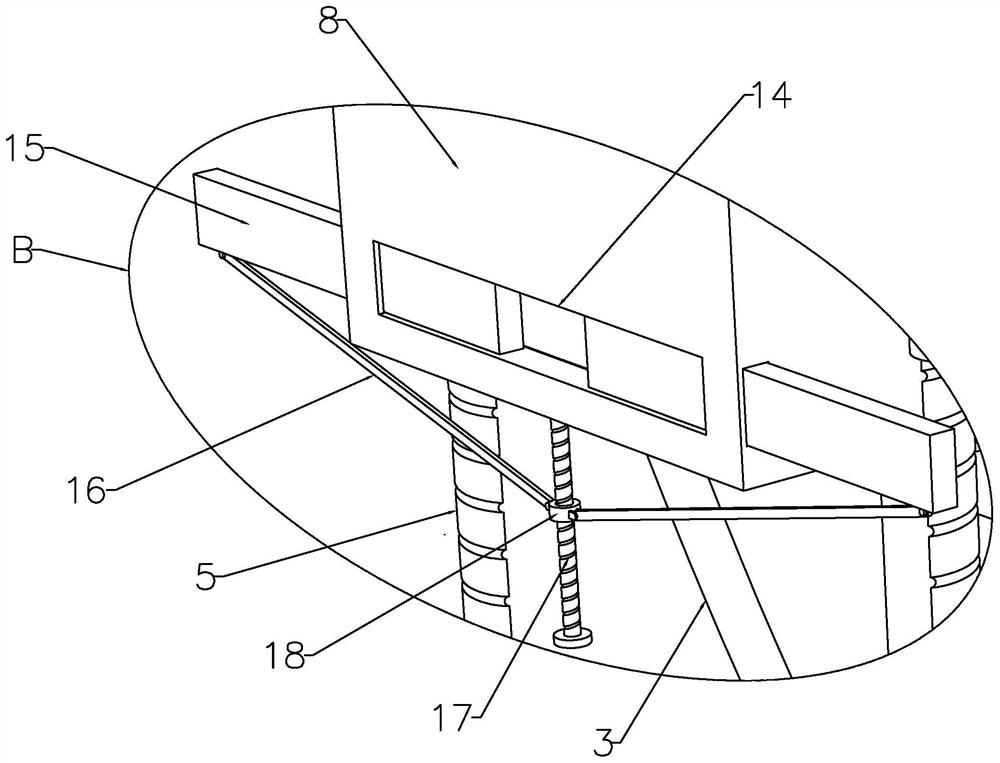
[0050] refer to image 3 , the both sides of the repair box 8 are slidingly installed with material limiting plates 15 that are symmetrically distributed, and the end of the material limiting plate 15 extends to the inside of the discharge port 14, and the bottom end of the repairing box 8 is provided with the material limiting plate 15. the adjustment mechanism.

[0051] refer to image 3 , the adjustment mechanism includes a hinged rod 16, an adjustment screw 17 and an adjustment collar 18, the bottom of the repair box 8 is rotated with an adjustment screw 17, and the threaded sleeve on the rod body of the adjustment screw 17 is provided with an adjustment collar 18, and the adjustment collar 18 A hinged rod 16 is hingedly installed between the two sides of each and the bottom ends of the two material limiting plates 15 respectively.

[0052] This embodiment adds a mechanism for adjusting the diameter of the discharge port 14 on the basis of the first and second embodiment...


PUM


Abstract

The invention discloses a concrete building surface defect repairing device and a repairing method thereof, relates to the field of concrete building surface defect repairing, and aims to solve the problems that existing concrete building wall surface repairing operation cannot achieve automatic treatment, so that the repairing efficiency is low, and certain danger exists during repairing operation. According to the technical scheme, the device comprises a movable vehicle body, a raw material box is fixedly installed on one side of the top end of the movable vehicle body, a first electric telescopic rod is fixedly installed on the other side, facing the movable vehicle body, of the raw material box, and a movable base is fixedly connected to the end of the first electric telescopic rod; and the movable base is slidably mounted at the top end of the movable vehicle body. The concrete surface defect repairing device can replace manpower to conduct repairing operation on defects of different sizes on the concrete surface, the repairing efficiency of the concrete surface defects is improved, and meanwhile the danger of repairing the concrete surface defects can be reduced.

Description

technical field [0001] The invention relates to the field of repairing surface defects of concrete buildings, in particular to a device for repairing surface defects of concrete buildings and a repairing method thereof. Background technique [0002] At present, in the field of construction engineering, wall structures with steel bars buried inside and poured concrete are widely used. Due to the high brittleness of concrete structures, cracks will inevitably appear on walls after long-term use, and in concrete After the pouring is completed, the surface is prone to voids due to incomplete vibration. If these cracks and voids are not dealt with in time, they will continue to grow, leading to a decrease in the watertightness of the concrete structure and leakage, affecting the service life of the wall, and some even It cannot be used and has a great security risk. [0003] The repair of existing concrete building surface defects is generally carried out manually, which not onl...

Claims


Application Information

Patent Timeline
IPC IPC(8): E04G23/02
CPCE04G23/0203
Inventor 安向左刘琴
Owner 安徽联赢环境建设有限公司
Why Eureka
Try Eureka