Supercharge Your Innovation With Domain-Expert AI Agents!

Interlocking protection method

A technology of interlocking protection and interlocking signal, applied in the direction of instruments, computer control, simulators, etc., can solve the problems that the quantity cannot meet the requirements of high-energy light source interlocking protection, the interlocking system is triggered by mistake, the system is complicated, etc., to prevent False triggering, high degree of integration and high stability

Pending Publication Date: 2022-03-15
INST OF HIGH ENERGY PHYSICS CHINESE ACADEMY OF SCI
View PDF0 Cites 0 Cited by
  • Summary
  • Abstract
  • Description
  • Claims
  • Application Information

AI Technical Summary

Problems solved by technology

[0003] The Institute of High Energy Physics of the Chinese Academy of Sciences has developed an interlock protection system based on the commercial ZYNQ development platform. The basic functions are similar, but because a commercial FPGA board is used, an external analog circuit needs to be added to convert the TTL signal and the switch signal. It is an LVTTL signal, which makes the system more complicated
Moreover, since the input and output signals are not photoelectrically isolated, when there are fluctuations in the power grid, false triggering of the interlock system will occur
In addition, due to the small number of I / O pins on the chip, a maximum of 16 channels of interlock protection system can only be built, which cannot meet the requirements of high-energy light source interlock protection in terms of quantity.

Method used


Image

  • Interlocking protection method
  • Interlocking protection method
  • Interlocking protection method

Examples


Embodiment Construction

[0039] The present invention will be described in further detail below in conjunction with the accompanying drawings.

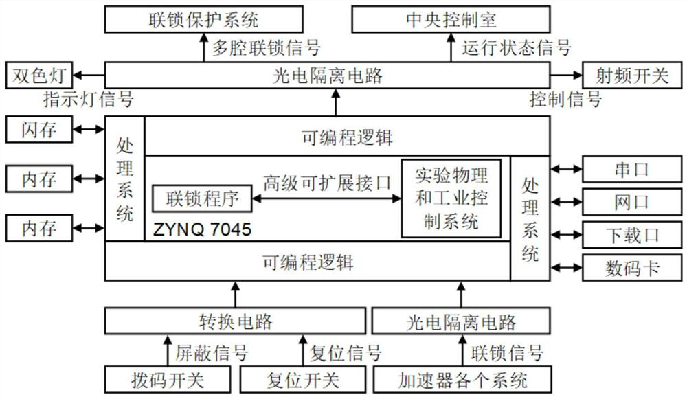
[0040] 1. Hardware design

[0041] The interlocking protection system collects interlocking signals from various systems of the accelerator. The designed interlocking board contains a total of 54 interlocking signal input channels. These interlocking signals are isolated by a photoelectric isolation circuit and convert TTL signals into LVTTL signals. And after switching between high and low levels, it is input to the FPGA chip. At the same time, each interlock signal can be shielded by a dial switch. When a channel is shielded, the interlock status of the corresponding channel will not affect the output of the RF switch control signal, that is, the channel is treated as normal. In addition, each interlocking signal also needs to have a two-color LED display light to display the interlocking status. The red light is always on to indicate failure, the green li...


PUM


Abstract

The invention discloses an interlocking protection method. Three types of interlocking signals are respectively input into an interlocking protection system of a high-frequency station, the first type of interlocking signals are interlocking signals generated by equipment in the high-frequency station, and the second type of interlocking signals are multi-cavity interlocking signals generated by other interlocking protection systems of the high-frequency station; the third-class interlocking signal is a signal generated by a high-frequency station association system; performing logic judgment according to the three types of interlocking signals to generate a radio frequency switch control signal, an indicator lamp signal, a multi-cavity interlocking signal and a state signal of a high-frequency system; when the output signal of each input channel is at a high level, that is, all the channels are in a normal state, the radio frequency switch control signal and the multi-cavity interlocking signal of the high-frequency station are at high levels, otherwise, the radio frequency switch control signal and the multi-cavity interlocking signal are at low levels; if the three types of interlocking signals are all normal, the standby state signal is a high level; when the high-frequency system outputs high-frequency power, the state monitoring signal of the radio frequency switch becomes high level, the operation state signal becomes high level, and otherwise, the operation state signal becomes low level.

Description

technical field [0001] The invention belongs to the technical field of accelerators, and in particular relates to an interlocking protection method, which is used for interlocking protection of high-frequency systems in boosters and storage rings of high-energy synchrotron radiation light source projects, and can be widely used in interlocking protection of related test systems. Background technique [0002] The high-frequency system is an extremely important system in the accelerator, which plays an important role in providing microwave power for the charged particle beam. The microwave power transmitted by the high-frequency system is very large, up to one or two hundred kilowatts. Once some equipment in the high-frequency system fails, such as the coupler sparking, it is necessary to quickly cut off the high-frequency power to prevent the ceramic window of the coupler from being damaged. If it is damaged, it will affect the stable operation of the accelerator. This functi...

Claims


Application Information

Patent Timeline
Patent Type & Authority Applications(China)
IPC IPC(8): G05B19/042H05H7/02
CPCG05B19/0423H05H7/02H05H2007/027G05B2219/25257
Inventor 邓子为林海英王群要戴建枰张沛
Owner INST OF HIGH ENERGY PHYSICS CHINESE ACADEMY OF SCI
Features
  • R&D
  • Intellectual Property
  • Life Sciences
  • Materials
  • Tech Scout
  • Unparalleled Data Quality
  • Higher Quality Content
  • 60% Fewer Hallucinations
Learn More