Optical probe mounting and debugging device for machining center and use method of optical probe mounting and debugging device

A technology for optical probes and machining centers, applied in metal processing equipment, metal processing machinery parts, manufacturing tools, etc., can solve the complex structure of optical measurement equipment and the inability to realize the cumbersome process of changing, installing, debugging, and maintaining multiple machining centers and other problems, to achieve the effect of simple and fast debugging process, wide range of use and wide range of angles

Pending Publication Date: 2022-03-18
TIANJIN NAVIGATION INSTR RES INST
View PDF6 Cites 0 Cited by
  • Summary
  • Abstract
  • Description
  • Claims
  • Application Information

AI Technical Summary

Problems solved by technology

[0008] However, the structure of the optical measuring equipment is complex, and the installation, commissioning, and maintenance processes are cumbersome, and it is impossible to replace multiple machining centers

Method used


Image

  • Optical probe mounting and debugging device for machining center and use method of optical probe mounting and debugging device
  • Optical probe mounting and debugging device for machining center and use method of optical probe mounting and debugging device
  • Optical probe mounting and debugging device for machining center and use method of optical probe mounting and debugging device

Examples


Embodiment Construction

[0048] The structure of the present invention will be further described below in conjunction with the accompanying drawings and through embodiments. It should be noted that this embodiment is illustrative rather than limiting.

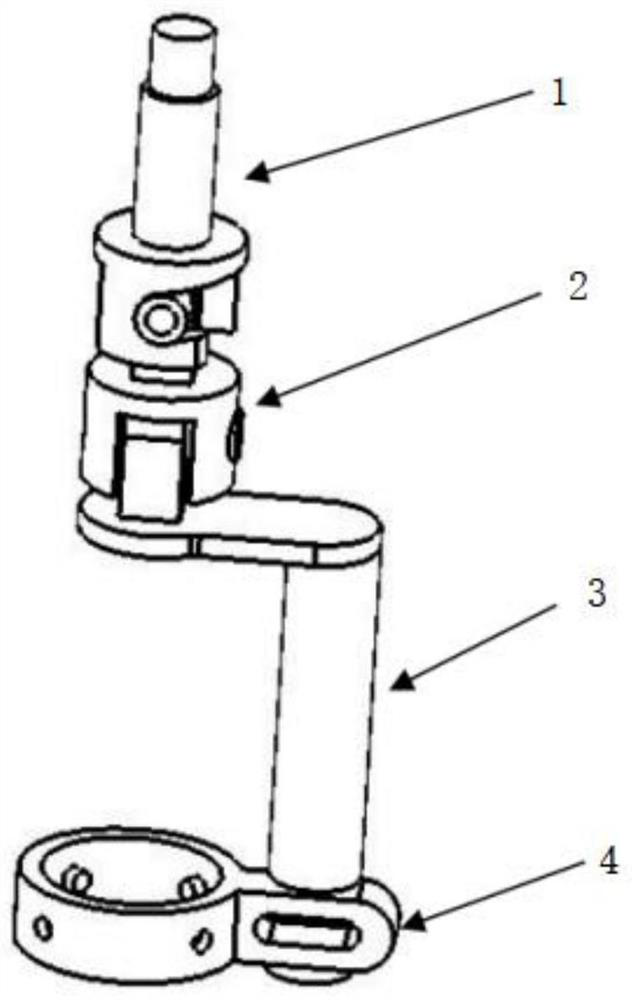
[0049] A device for installing and debugging an optical probe on a machining center, please refer to Figure 1-5 , including a mounting head 1 , a first rotating adjustment member 2 , a second rotating adjusting member 3 and an optical probe fixing member 4 .

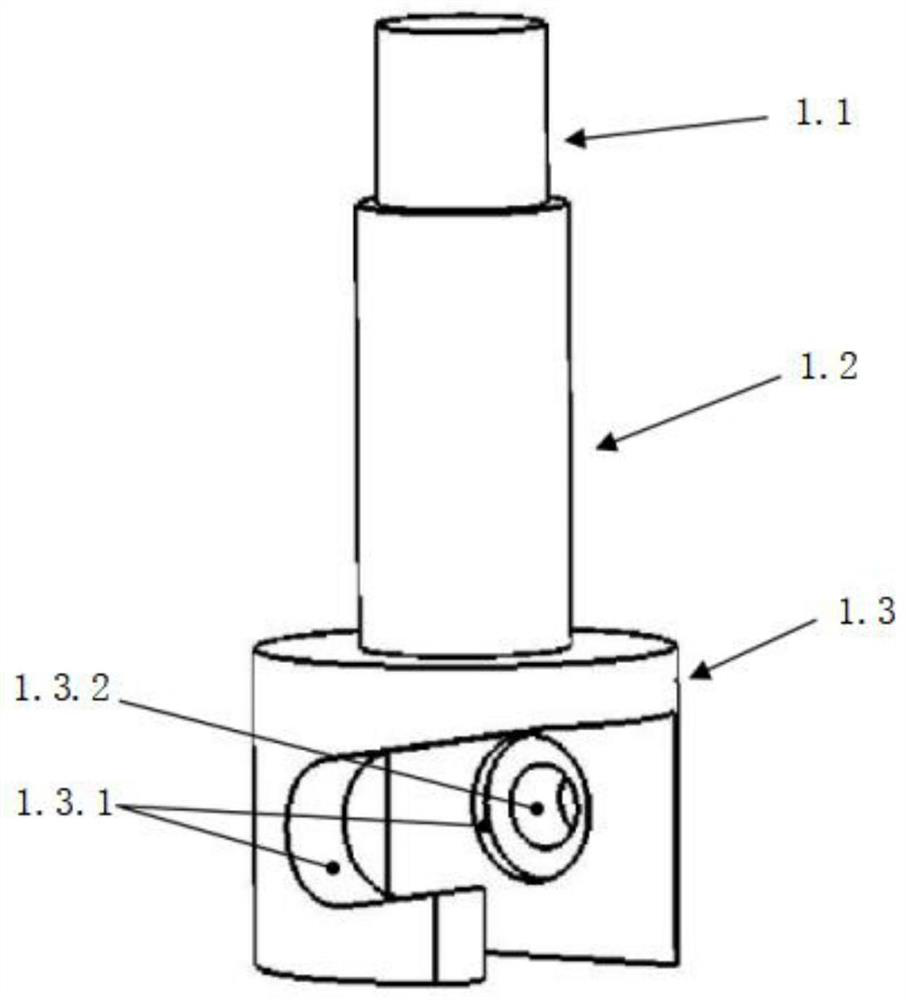
[0050] The installation head is a three-stage structure, the top 1.1 of the installation head is an external thread column structure that can be fixedly connected with the magnetic table base, the middle part 1.2 of the installation head is a general tool handle installation column structure, and the bottom 1.3 of the installation head is provided with The hollow cylinder structure with side openings is provided with a circular positioning groove 1.3.1 along the Y-axis direction on the hollow c...


PUM


Abstract

The invention relates to an optical probe mounting and debugging device for a machining center and a using method, the device comprises a mounting head, and the mounting head is mounted on a general tool handle or a magnetic gauge stand of a machine tool and is used for positioning and fastening in the machine tool; comprising a rotary adjusting structure, the rotary adjusting structure is connected to the lower portion of the mounting head and comprises a first rotary adjusting piece and a second rotary adjusting piece, the first rotary adjusting piece is fixedly connected with the lower end of the mounting head in a rotary adjusting mode along the Y axis, and the upper end of the second rotary adjusting piece is fixedly connected with the lower end of the first rotary adjusting piece in a rotary adjusting mode along the X axis; comprising an optical probe fixing piece, the optical probe fixing piece is connected with the lower end of a second rotary adjusting piece in a transverse adjustable mode, a mounting ring is arranged at the end, away from the end connected with the second rotary adjusting piece, of the optical probe fixing piece, and a plurality of radial jackscrew holes are evenly distributed in the side wall of the mounting ring in the circumferential direction; a fine adjustment jackscrew is installed in each radial jackscrew hole, and the electron microscope is fastened in the installation ring through the fine adjustment jackscrews. The method is high in measurement precision and wide in application range.

Description

technical field [0001] The invention belongs to the technical field of machining, and in particular relates to a device for installing and debugging an optical probe on a machining center and a method for using it. Background technique [0002] During the machining process of the stone machining center, the workpiece will be affected by factors such as machining deformation error, clamping error, measurement error, tool clamping error, tool wear error, and environmental temperature and humidity, resulting in corresponding deviations in the accuracy of the processed workpiece. In order to obtain qualified dimensional accuracy, shape accuracy, position accuracy and surface quality, it is necessary to continuously adjust the processing data. The main method is to use the corresponding measuring tools or measuring instruments to detect whether the workpiece meets the requirements of the drawing, and provide the feed rate according to the measurement data in the subsequent proces...

Claims


Application Information

Patent Timeline
Patent Type & Authority Applications(China)
IPC IPC(8): B23Q17/24
CPCB23Q17/2471
Inventor 尹德智张涌禄马明山王强尹滦于金洽高建
Owner TIANJIN NAVIGATION INSTR RES INST
Why Eureka
Try Eureka