Power rail circuit for high-voltage Buck converter

A converter and power rail technology, which is used in high-efficiency power electronic conversion, conversion of DC power input to DC power output, instruments, etc. Suitable for low power requirements and other issues, to achieve the effect of small changes, reduced power consumption, and high stability

Active Publication Date: 2022-03-18
UNIV OF ELECTRONICS SCI & TECH OF CHINA +1
View PDF6 Cites 1 Cited by
  • Summary
  • Abstract
  • Description
  • Claims
  • Application Information

AI Technical Summary

Problems solved by technology

There are the following disadvantages in using the voltage regulator tube to realize the pre-step down: the performance of the integrated voltage regulator tube is greatly affected by the process, and the way of using the voltage regulator tube to realize the pre-down voltage has a large power consumption
Therefore, the above-mentioned power rail circuit is not suitable for application in high-voltage Buck converters with higher requirements for low power consumption.

Method used


Image

  • Power rail circuit for high-voltage Buck converter
  • Power rail circuit for high-voltage Buck converter
  • Power rail circuit for high-voltage Buck converter

Examples


Embodiment Construction

[0015] The technical solution of the present invention will be described in detail below in conjunction with the accompanying drawings and specific embodiments.

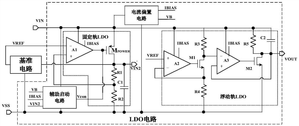
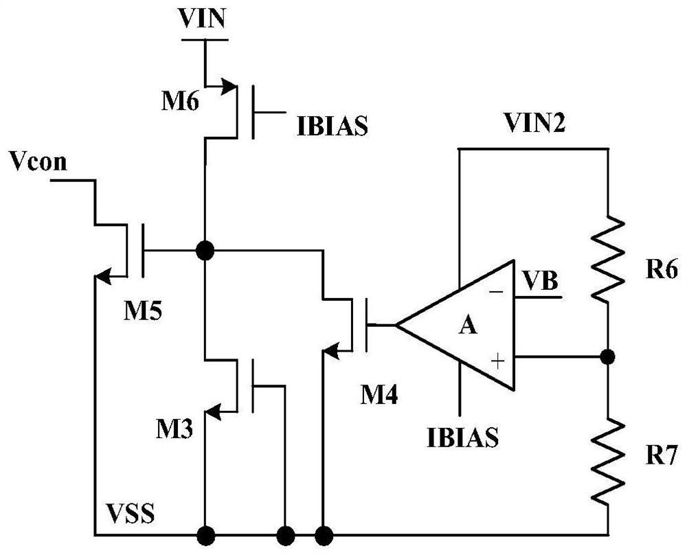
[0016] figure 1 It is a schematic diagram of the overall structure of the power rail circuit of the high-voltage Buck converter proposed by the present invention. Including LDO circuit and reference circuit. Among them, the LDO circuit includes a current bias circuit, an auxiliary start-up circuit, a fixed-rail LDO circuit, and a floating-rail LDO circuit. figure 2 The circuit diagram for auxiliary start.

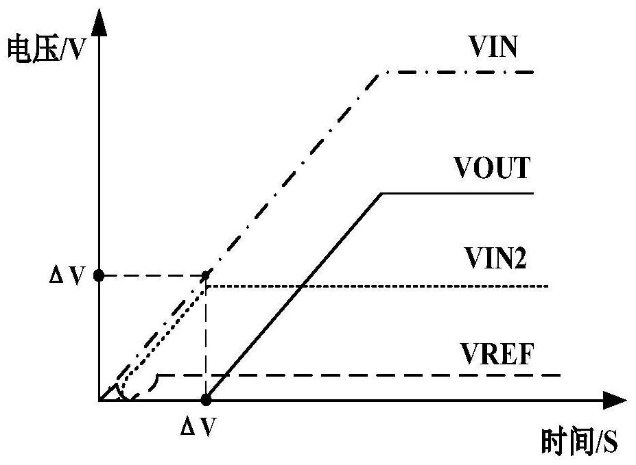
[0017] The current bias circuit generates the bias current IBIAS required by each module inside the LDO and the reference voltage VB of the auxiliary start-up circuit; the auxiliary start-up circuit compares the output signal of the fixed-rail LDO in the initial power-on stage when the reference circuit is not established. The divided voltage signal of VIN2 and the reference voltage VB, the control signal Vcon...


PUM


Abstract

The invention belongs to the technical field of electronic circuits, and particularly relates to a power rail circuit for a high-voltage Buck converter. According to the power rail circuit for the high-voltage Buck converter, a pre-step-down module is omitted through a simple auxiliary starting circuit, power consumption is reduced while the circuit structure is simplified, and the function of low power consumption of a power rail is achieved. The whole Buck converter realizes starting of an input current source as low as [mu] A level, and is in a low-power-consumption state in the whole standby process. Compared with the clamping of a diode connection mode, the floating rail LDO clamped by the operational amplifier has the advantage that the influence of the process on the output VOUT signal is small. The whole power rail circuit does not use an integrated voltage-regulator tube, and the output of the power rail circuit is small in change and high in stability under the full process angle.

Description

technical field [0001] The invention belongs to the technical field of electronic circuits, and in particular relates to a power rail circuit used for a high-voltage Buck converter. Background technique [0002] With the continuous advancement of energy saving and emission reduction policies, the market demand for low power consumption products has increased sharply. Taking a switching power supply as an example, in a high-voltage Buck converter, the power rail circuit is usually used to supply power to the internal circuit modules to reduce the internal power consumption of the switching power supply, so that the power consumption of the entire electronic product is lower. In a traditional high-voltage Buck converter, the internal power rail circuit consists of a pre-step-down module, a reference module and an LDO module. The implementation of the power rail is to pre-step down through the voltage regulator tube to obtain a rough voltage to supply power to the subsequent r...

Claims


Application Information

Patent Timeline
Patent Type & Authority Applications(China)
IPC IPC(8): H02M3/155H02M1/36
CPCH02M3/155H02M1/36Y02B70/10
Inventor 罗萍樊捷陈嘉豪王浩杨楠何致远宋浩
Owner UNIV OF ELECTRONICS SCI & TECH OF CHINA
Why Eureka
Try Eureka