Heat transfer double-layer pipe, inner pipe for heat transfer double-layer pipe and manufacturing method of inner pipe

A manufacturing method and double-layer tube technology, which are applied in the directions of heat exchanger ducts, fixed tubular duct assemblies, tubular elements, etc., can solve problems such as insufficient heat exchange, and achieve the purpose of suppressing the reduction of heat exchange performance and reducing narrowness. The effect of miniaturization

Pending Publication Date: 2022-03-18
FURUKAWA SKY ALUMINUM CORP
View PDF3 Cites 0 Cited by
  • Summary
  • Abstract
  • Description
  • Claims
  • Application Information

AI Technical Summary

Problems solved by technology

[0004] In a system that uses a compressor to compress the gaseous refrigerant discharged from the evaporator, if the refrigerant cannot be sufficiently vaporized, that is, when the refrigerant flows into the compressor while the liquid is mixed into the gas, a Unfavorable conditions such as insufficient heat exchange

Method used


Image

  • Heat transfer double-layer pipe, inner pipe for heat transfer double-layer pipe and manufacturing method of inner pipe
  • Heat transfer double-layer pipe, inner pipe for heat transfer double-layer pipe and manufacturing method of inner pipe
  • Heat transfer double-layer pipe, inner pipe for heat transfer double-layer pipe and manufacturing method of inner pipe

Examples


Embodiment 1

[0058] use Figure 1 to Figure 7 Examples of the heat transfer double pipe and the inner pipe for the heat transfer double pipe described above will be described.

[0059] Such as Figure 6 as well as Figure 7 As shown, the inner tube 2 for the heat transfer double-layer tube of this example is used for the fluid flowing inside the inner tube 2 arranged inside the outer tube 10, and the fluid flowing between the inner tube 2 and the outer tube 10. The inner tube 2 is used for heat exchange between the heat transfer double-layer tube 1 .

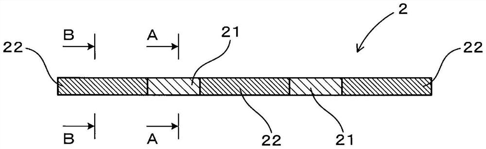
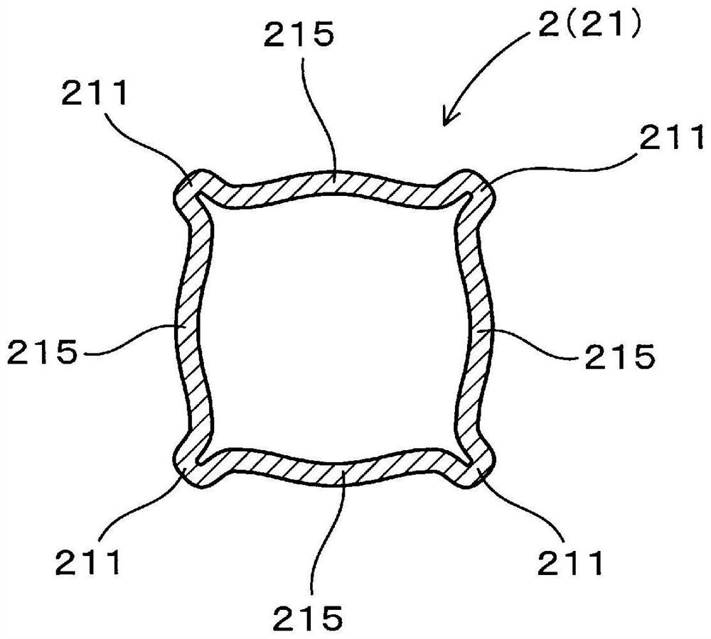
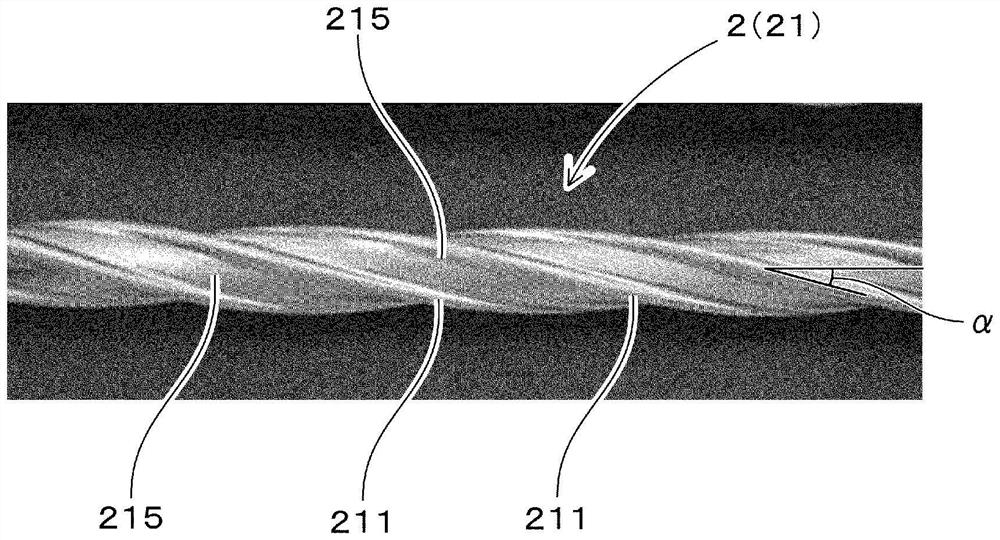
[0060] Such as figure 1 As shown, the inner tube 2 has a first region 21 and a second region 22 with different cross-sectional shapes. Such as figure 2 and image 3 As shown, the first region 21 has a plurality of first protrusions 211 protruding outward, and has a first concave-convex shape in which the positions of the first protrusions 211 are displaced helically in the length direction. Such as Figure 4 and Figure 5 As shown,...

Embodiment 2

[0069] In this example, a modified example of the inner tube 2 for a heat transfer double tube described in Example 1 is shown.

[0070] Such as Figure 8 and Figure 9 As shown, the inner pipe 202 for the heat transfer double-layer pipe of this example has a plurality of first regions 21 and second regions 22 in the longitudinal direction, and has a third smooth pipe shape with a circular cross-sectional shape at both ends. Area 23.

[0071] When the inner tube 202 of this example is used to form a double tube, since the third regions 23 at both ends have a smooth tube shape, they can be easily used as seams for connection with other parts. Therefore, practicality can be further improved. In addition, the above-mentioned third region 23 may be appropriately sandwiched between the first region 21 and the second region 22 , for example.

Embodiment 3

[0073] This example relates to the manufacturing method of the inner tube 2 for the heat transfer double-layer tube of the first embodiment.

[0074] In this example, an inner pipe blank 20 having a smooth pipe shape having a circular cross-sectional shape is prepared, and a Figure 10 ~ Figure 12 The shown inner tube shaping device 5 shapes the inner tube. Such as Figure 10 As shown, the inner tube forming device 5 is disposed between the inlet crawler belt 71 and the outlet crawler belt 72 at the front and rear thereof. Furthermore, the entry-side crawler belt 71 and the exit-side crawler belt 72 have the inner pipe blank 20 and the inner pipe 2 that are inserted into the inner pipe forming device 5 while applying appropriate tension to the inner pipe blank 20 and the formed inner pipe 2 . A function to move along the axis. In addition, on the upstream side of the crawler belt 71 of the entry side, a supply device, a straightening machine, a cleaning machine, etc. A cut...


PUM


Abstract

An inner tube (2) used in a heat transfer double-layer tube that exchanges heat between a fluid flowing inside the inner tube (2) disposed inside an outer tube and a fluid flowing between the inner tube (2) and the outer tube. The inner tube (2) has a first region (21) and a second region having different cross-sectional shapes, and the first region (21) has a plurality of first protrusions (211) protruding outward and has a first concave-convex shape in which the positions of the first protrusions (211) are displaced helically in the longitudinal direction. The second region has a plurality of second protrusions protruding outward at positions, the number of the second protrusions is larger than the number of the first protrusions, and the second region has a second concave-convex shape in which the positions of the second protrusions are displaced helically in the longitudinal direction.

Description

technical field [0001] The present invention relates to a heat transfer double layer tube that can be applied to, for example, a heat exchange cycle of an air conditioner for an automobile. Background technique [0002] The heat exchange cycle (also called refrigeration cycle) of automobile air conditioners and the like is equipped with a condenser, an evaporator, a compressor, and an expansion valve, and uses Freon, CO 2 , ammonia, and other refrigerants circulate in the circulation path connecting them. In such a heat exchange cycle, it is proposed that a double tube is arranged in the circulation path, and the high-temperature refrigerant coming out of the condenser and the low-temperature refrigerant coming out of the evaporator are separated in the two-layer space formed by the double tube. Refrigerants flow in opposite directions to perform heat exchange, thereby improving heat exchange performance (see Patent Documents 1 and 2). [0003] On the other hand, as refrig...

Claims


Application Information

Patent Timeline
Patent Type & Authority Applications(China)
IPC IPC(8): B60H1/00B60H1/32
CPCB60H1/00321B60H1/3227F28F1/06F28D7/106F28F1/426F28F2210/06F16L9/006F16L9/19F28F1/08
Inventor 片平史郎中村拓郎
Owner FURUKAWA SKY ALUMINUM CORP
Why Eureka
Try Eureka