
Intelligent welding device for computer hardware machining

A computer hardware and welding device technology, which is applied in the field of intelligent welding devices for computer hardware processing, can solve the problems of easy shaking in dust removal operations, lower work efficiency, and inconvenient use, so as to improve functional diversity, improve work efficiency, and structure simple effect

Inactive Publication Date: 2022-03-22
金乡县恒业商贸有限公司
View PDF1 Cites 1 Cited by
  • Summary
  • Abstract
  • Description
  • Claims
  • Application Information

AI Technical Summary

Problems solved by technology

[0003] According to a Chinese patent (publication number: CN208050555U), an intelligent welding device for computer hardware processing is proposed. In this patent, a movable groove is provided on the surface of the placing plate, and a movable plate is provided for sliding on the surface of the movable groove. At the same time, the upper surface of the movable plate A negative pressure dust collector is fixedly installed on the surface. By setting a movable frame, the negative pressure dust collector can slide back and forth on the surface of the movable frame. And the inside of the roller groove, so that the negative pressure dust collector can slide left and right on the surface of the mounting seat. The two sides of the mounting seat are symmetrically provided with clamping plates, and the main board can be clamped between the adjacent two clamping plates. Negative pressure dust removal The machine can clean the dust on the surface of the main board by sliding, but the main board cannot be rotated during the dust removal process. It needs to be removed and flipped to the other side to re-lock to continue the dust removal operation, which reduces work efficiency and is inconvenient to use. Multiple structures are needed to realize the front and rear and left and right movement of the negative pressure dust collector, and there is no necessary fixed clamping structure for the main board, so it is easy to shake during the dust removal operation

Method used


Image

  • Intelligent welding device for computer hardware machining
  • Intelligent welding device for computer hardware machining
  • Intelligent welding device for computer hardware machining

Examples


Embodiment Construction

[0024] The present invention will be further described below in conjunction with the examples.

[0025] The following examples are used to illustrate the present invention, but cannot be used to limit the protection scope of the present invention. The conditions in the embodiment can be further adjusted according to the specific conditions, and the simple improvement of the method of the present invention under the premise of the concept of the present invention belongs to the protection scope of the present invention.

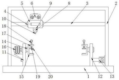
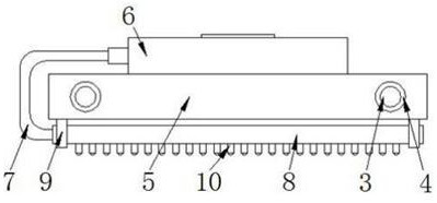
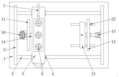
[0026] see Figure 1-4 , the present invention provides an intelligent welding device for computer hardware processing, comprising a substrate 1, a frame 2 is welded on the upper surface of the substrate 1, and a slide bar 3 is fixedly installed on the inner side wall of the frame 2, and the number of the slide bar 3 is two. figure 1 , figure 2 and image 3 When people lean on the handrail to drive the support plate 5 to move left and right, the support pl...


PUM


Abstract

The invention discloses an intelligent welding device for computer hardware machining, and belongs to the technical field of computer hardware machining. The intelligent welding device comprises a base plate, a frame is welded to the upper surface of the base plate, a sliding rod is fixedly installed on the inner side wall of the frame, the outer surface of the sliding rod is sleeved with a sliding sleeve, and the sliding sleeve is clamped to the left side face of a supporting plate; by arranging the mounting plate a, the mounting plate b, the rotating shaft a, the U-shaped locking seat and the locking plate, the electric push rod extends or contracts to drive the mounting plate b to move left and right, so that the distance between the mounting plate a and the mounting plate b is adjusted, and clamping and dust removing operation on different main plates is met; the threaded column rotates to drive the locking plate to move downwards to be matched with the U-shaped locking seat to clamp and fix the mainboard, the clamping stability is good, the driving motor drives the rotating shaft a to rotate, the mainboard is driven to rotate through the U-shaped locking seat, overturning of the mainboard is achieved without releasing fixation, the working efficiency is improved, and use is convenient.

Description

technical field [0001] The invention belongs to the technical field of computer hardware processing, and in particular relates to an intelligent welding device for computer hardware processing. Background technique [0002] Computer hardware refers to the total of various physical devices composed of electronic, mechanical and photoelectric components in a computer system. These physical devices form an organic whole according to the requirements of the system structure to provide a material basis for the operation of computer software. In short, computer hardware The function of the computer is to input and store programs and data, and execute the program to process the data into a usable form. When the user needs it, the data is output in the manner required by the user. The main box mainly includes CPU, memory, motherboard, Hard disk drive, CD-ROM drive, various expansion cards, cables, power supply, etc., external devices include mouse, keyboard, etc. [0003] According...

Claims


Application Information

Patent Timeline
Patent Type & Authority Applications(China)
IPC IPC(8): B23K37/04B23K37/00B08B5/04
CPCB23K37/0435B23K37/00B08B5/04
Inventor 姜国占刘刚赵庆姜贺夏宇天
Owner 金乡县恒业商贸有限公司
Learn More