High-precision aerated concrete block production device

A technology of aerated concrete and production equipment, which is applied in the direction of ceramic forming machines and manufacturing tools to achieve the effects of accelerating cutting speed, improving adaptability and improving work efficiency

Pending Publication Date: 2022-03-22
绍兴高新技术产业开发区迪荡新城投资发展有限公司
View PDF9 Cites 1 Cited by
  • Summary
  • Abstract
  • Description
  • Claims
  • Application Information

AI Technical Summary

Problems solved by technology

[0005] The invention provides a high-precision aerated concrete block production device,

Method used


Image

  • High-precision aerated concrete block production device
  • High-precision aerated concrete block production device
  • High-precision aerated concrete block production device

Examples


Embodiment 1

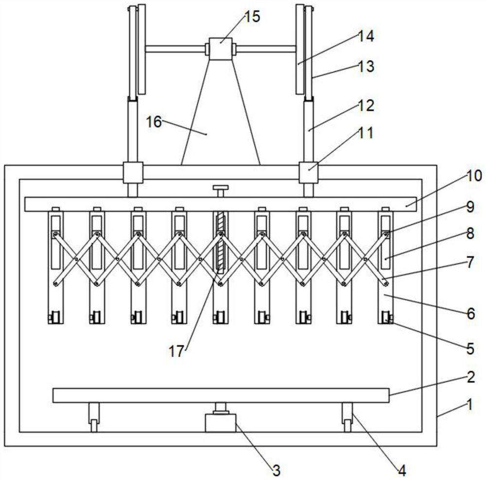
[0054] The embodiment of the present invention provides a high-precision aerated concrete block production device, such as Figure 1-2 shown, including:

[0055] Frame 1 can be a rectangular frame, and moving wheels can also be installed at the bottom of the rectangular frame for easy movement;

[0056] The workbench 2 installed on the frame 1, in this embodiment, the workbench 2 is fixed on the output shaft of the first motor 3, the first motor 3 is fixed on the frame 1, and can be fixed by bolts, the workbench 2 There are multiple support legs 4 fixed at the bottom, and rollers are installed at the bottom of the support legs 4, which can drive the workbench 2 to rotate through the first motor 3, and the workbench 2 drives the aerated concrete on it to rotate to set the angle and adjust the cutting position;

[0057] A cutting assembly arranged above the workbench 2, the cutting assembly includes a plurality of steel wires arranged in parallel at intervals;

[0058] An adjust...

Embodiment 2

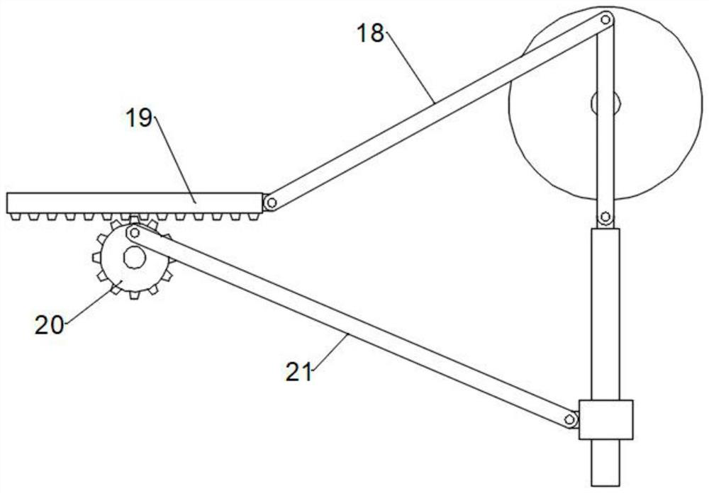
[0075] This embodiment is on the basis of embodiment 1, as image 3 As shown, transmission parts are also included, and the transmission parts include:

[0076] The second connecting rod 18, one end of the second connecting rod 18 is hinged with the first connecting rod 13 and the turntable 14, the other end of the second connecting rod 18 is hinged with a rack 19, and the rack 19 is slidably mounted on the frame 1 On, the sliding seat and the sliding rail can be used to cooperate;

[0077] The gear 20 is used to mesh with the rack 19, and it is rotatably mounted on the frame 1;

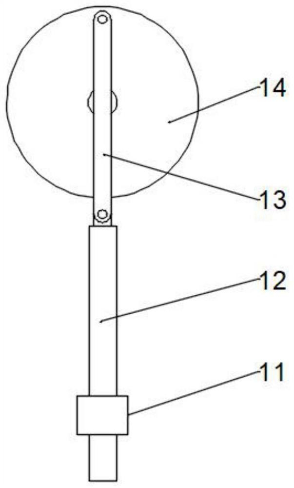
[0078] The third connecting rod 21, one end of which is eccentrically hinged to the end face of the gear 20, and the other end is hinged to the guide sleeve 11, and the guide sleeve 11 is longitudinally slidably mounted on the frame 1;

[0079] In this embodiment, when the turntable 14 rotates, the second connecting rod 18 drives the rack 19 to reciprocate, the rack 19 drives the gear 20 to rotate ...

Embodiment 3

[0081] This embodiment is on the basis of embodiment 2, as Figure 4-5 As shown, a cleaning assembly is also included for cleaning the steel wire, and the cleaning assembly includes:

[0082] Sleeve 25 is sleeved on the outside of the steel wire and close to the side wall of the inverted U-shaped plate 6. The inner wall of the sleeve 25 is provided with ribs at intervals in the circumferential direction, and the sides of the ribs are preferably arc-shaped;

[0083] Connected to the fourth connecting rod 24 on the sleeve 25, the fourth connecting rod 24 is eccentrically hinged with the disk 23;

[0084] The third motor 26 fixed on the side wall of the inverted U-shaped plate 6, the third motor 26 is used to drive the disc 23 to rotate;

[0085] Two symmetric cone rollers 22 that are located on the other side wall of the inverted U-shaped plate 6 can be provided with some pulverizing teeth on the surface of the cone roller 22, and the two cone rollers 22 are positioned at both ...


PUM


Abstract

The invention is suitable for the technical field of concrete production, and provides a high-precision aerated concrete block production device which comprises a rack; the workbench is mounted on the rack; the cutting assembly is arranged above the workbench and comprises a plurality of steel wires which are arranged in parallel at intervals; the adjusting assembly is used for synchronously adjusting the distance between adjacent steel wires, the transmission part comprises a second connecting rod, a rack, a gear and a third connecting rod, one end of the third connecting rod is eccentrically hinged to the end face of the gear, the other end of the third connecting rod is hinged to a guide sleeve, and the guide sleeve is longitudinally installed on the rack in a sliding mode; according to the aerated concrete cutting device, aerated concrete can be cut at the same time through the multiple steel wires, the working efficiency is improved, the distance between the steel wires is adjusted through the adjusting assembly, the aerated concrete can be cut into blocks of different sizes, and the adaptability is improved; and the transmission part is arranged, the steel wire is driven to gradually descend, meanwhile, longitudinal reciprocating cutting is conducted, aerated concrete cutting is facilitated, and the cutting speed is increased.

Description

technical field [0001] The invention belongs to the technical field of concrete production, and in particular relates to a high-precision aerated concrete block production device. Background technique [0002] Air-entrained concrete is made of siliceous materials (sand, fly ash and silicon-containing tailings, etc.) , pre-curing, cutting, autoclaving, curing and other processes made of lightweight porous silicate products, aerated concrete has made a contribution to saving land resources, simple production, low cost, and convenient masonry; [0003] During the processing of aerated concrete, large blocks need to be cut into small pieces, which is convenient for subsequent masonry operations. Chinese patent CN209552035U discloses an autoclaved aerated concrete block cutting device, including a processing table. There are two sets of support plates vertically connected to the table, and the support plates are respectively arranged at both ends of the processing table, and cut...

Claims


Application Information

Patent Timeline
IPC IPC(8): B28B11/12B28B11/14
CPCB28B11/12B28B11/14
Inventor 王世华
Owner 绍兴高新技术产业开发区迪荡新城投资发展有限公司
Why Eureka
Try Eureka