Deodorizing kitchen waste treatment equipment

A technology for kitchen waste and treatment equipment, which is applied to the removal of solid waste, the cleaning method using liquid, and the removal of smoke and dust. It can solve the problems of equipment such as strong odor, lack of flushing, and poor sealing performance, and achieve a safety mechanism. High, avoid odor emission, good flushing efficiency

Pending Publication Date: 2022-03-25
德清华得环保设备有限公司
View PDF11 Cites 0 Cited by
  • Summary
  • Abstract
  • Description
  • Claims
  • Application Information

AI Technical Summary

Problems solved by technology

[0005] The present invention provides an anti-odor kitchen waste treatment equipment, one of which is to have the anti-odor function and solve the problem of a large amount of odor genera

Method used


Image

  • Deodorizing kitchen waste treatment equipment
  • Deodorizing kitchen waste treatment equipment
  • Deodorizing kitchen waste treatment equipment

Examples


Embodiment 1

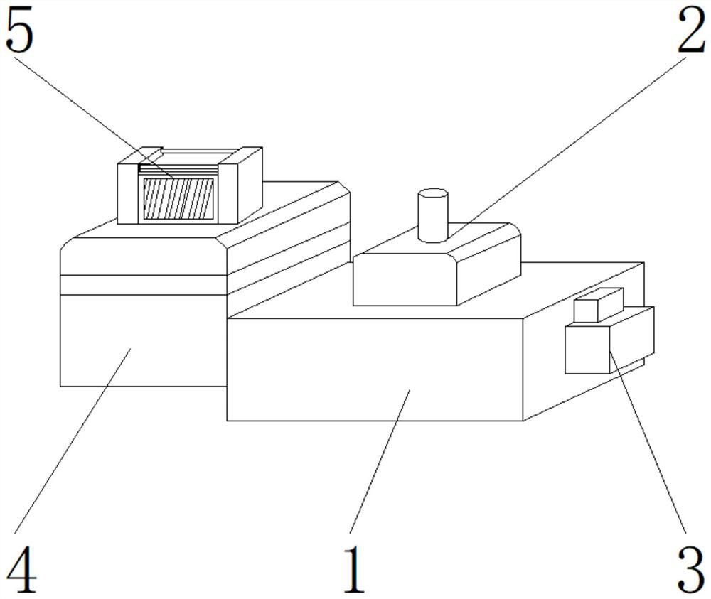
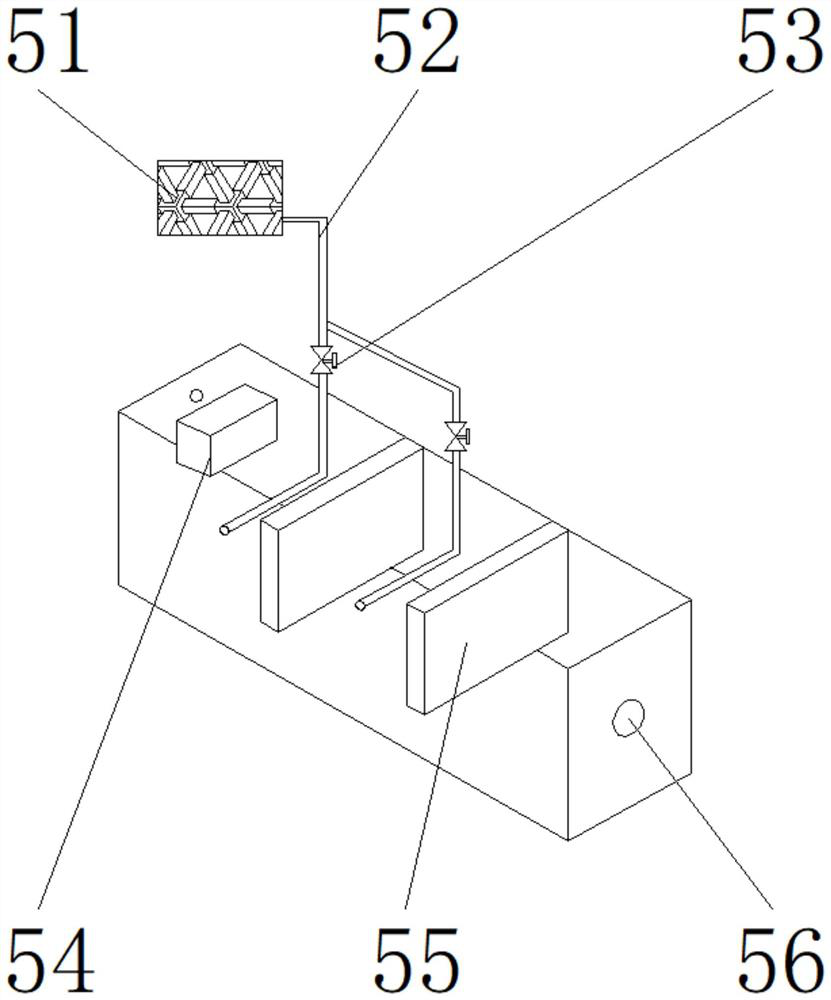
[0029] like Figure 1-5 As shown, the present invention provides a deodorant kitchen waste treatment device, comprising a main body 1, a sealing mechanism 3 is arranged on one side of the main body 1, a flushing device 2 is arranged on the upper end of the main body 1, and the other side of the main body 1 is arranged There is a stocking box 4, and the upper end of the stocking box 4 is provided with a deodorizing device 5; the deodorizing device 5 includes a grease decomposition mechanism 51, a microporous aeration pipe 52, a regulating valve 53, a trash basket 54, a partition 55, and a water outlet 56. , the microporous aeration pipe 52 is located on one side of the grease decomposition mechanism 51, and the regulating valve 53 is located on the outer wall of the microporous aeration pipe 52; The upper end of the microporous aeration pipe 52 is fixedly connected to one side of the grease decomposition mechanism 51 through the connecting hole, the trash basket 54 is located a...

Embodiment 2

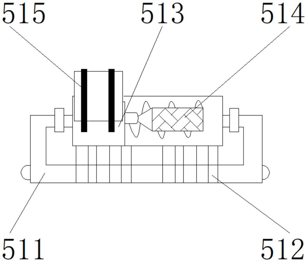
[0032] like Figure 1-5 As shown, on the basis of Embodiment 1, the present invention provides a technical solution: preferably, the grease decomposition mechanism 51 includes a connecting pipeline 511, an aerator 512, a plasma generator 513, an ozone generator 514, a positive and negative ion generator The aerator 515, the aerator 512 is located at the upper end of the connecting pipeline 511, the plasma generator 513 is located at the upper end of the aerator 512, the positive and negative ion generator 515 is located at the upper end of the plasma generator 513, and the ozone generator 514 is located at the upper end of the plasma generator 513. On one side, a wire is provided between the aerator 512 and the plasma generator 513 , the output end of the aerator 512 is electrically connected to the input end of the plasma generator 513 through the wire, and the connection between the plasma generator 513 and the ozone generator 514 A connection line is provided, and the outpu...

Embodiment 3

[0035] like Figure 1-5 As shown, on the basis of Embodiment 1, the present invention provides a technical solution: preferably, the sealing mechanism 3 includes a rotating shaft 31, a shaft hole 32, a baffle 33, a cover plate 34, and a sealing gasket 35, and the shaft hole 32 is located at the rotating shaft On both sides of 31, the baffle 33 is located on one side of the shaft hole 32, the gasket 35 is located on one side of the baffle 33, the cover plate 34 is located on one side of the gasket 35, and a welding is provided between the baffle 33 and the shaft hole 32. One side of the baffle plate 33 is fixedly connected to one side of the shaft hole 32 through a welding block, a screw is provided between the gasket 35 and the cover plate 34, and one side of the cover plate 34 is fixed to one side of the gasket 35 by screws For connection, a threaded groove is provided between the rotating shaft 31 and the shaft hole 32 , and the lower end of the rotating shaft 31 is detachab...


PUM


Abstract

The invention discloses deodorization kitchen waste treatment equipment, and relates to the technical field of kitchen waste treatment equipment, the deodorization kitchen waste treatment equipment comprises a main body, one side of the main body is provided with a sealing mechanism, the upper end of the main body is provided with a flushing device, the other side of the main body is provided with a material preparation box, and the upper end of the material preparation box is provided with a deodorization device. Under the combined action of a circulating water pump, a control valve, a water pipe, a flushing pipe and a protective sleeve, the equipment can have a cleaning function, kitchen waste is flushed, peculiar smells are not likely to be generated, and therefore the deodorization function is achieved; according to the invention, various forms of catering waste grease can be decomposed, secondary pollution is not generated, the grease is decomposed into hydrophilic molecules, the decomposition speed is high, the efficiency is high, the deodorization function of the equipment is obvious, and illegal cooking oil is fundamentally eliminated.

Description

technical field [0001] The invention relates to the technical field of kitchen waste processing equipment, in particular to a odor-proof kitchen waste processing equipment. Background technique [0002] With the continuous development of my country's economy and the continuous improvement of people's living standards, the catering industry in various cities has also entered a stage of rapid development, but the accompanying domestic waste and kitchen waste have seriously polluted urban environmental sanitation, especially these Some odors emitted by garbage affect the lives of the majority of people and bring great harm to the health of the majority of people. Therefore, there is an urgent need for a food waste treatment equipment that can deodorize. The following problems exist for the prior art: [0003] 1. The existing kitchen waste treatment equipment has poor sealing performance, often emits peculiar smell, and does not have the ability to clean the kitchen waste; [0...

Claims


Application Information

Patent Timeline
IPC IPC(8): B09B3/00B09B5/00B08B3/02B08B15/02B09B101/70
CPCB09B3/00B09B5/00B08B3/02B08B15/02
Inventor 李光华
Owner 德清华得环保设备有限公司
Why Eureka
Try Eureka