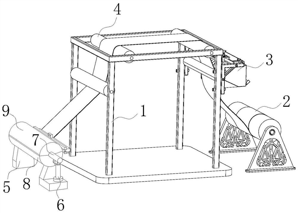
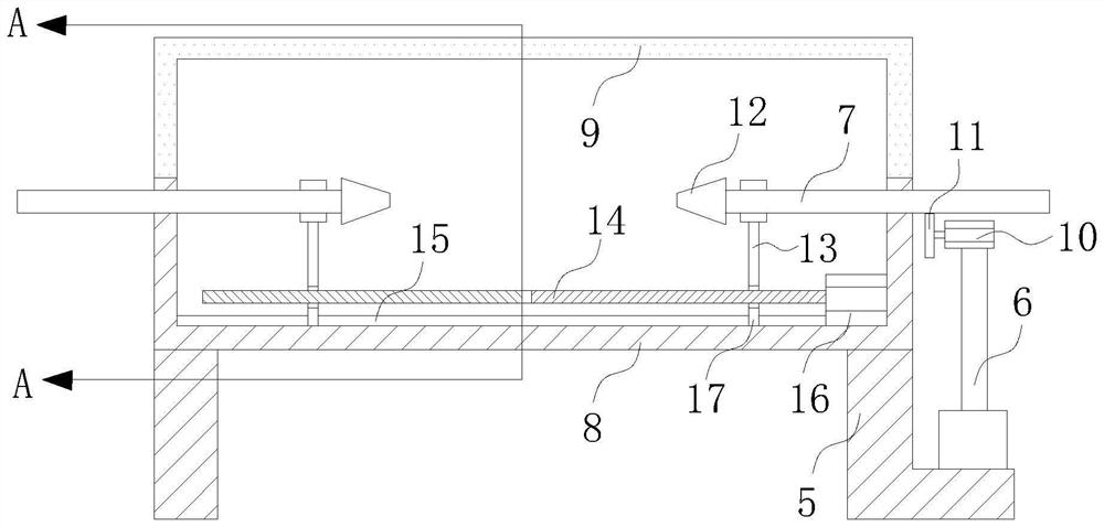
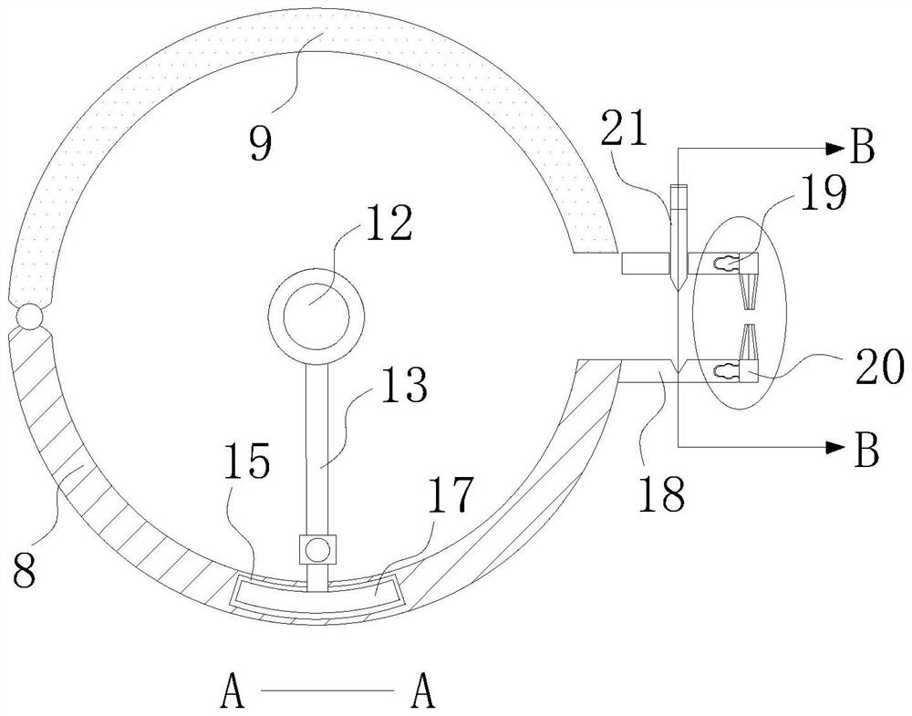
Printing machine with flexographic printing head

A printing head and printing machine technology, applied to printing machines, rotary printing machines, rotary printing machines, etc., can solve problems such as untimely supply of pigments, cuts to staff, irregular cuts, etc., to improve aesthetics and ease The effect of cutting materials and operation is simple and convenient

Pending Publication Date: 2022-03-25
花怀坤
View PDF1 Cites 0 Cited by
  • Summary
  • Abstract
  • Description
  • Claims
  • Application Information

AI Technical Summary

Problems solved by technology

[0004] The printing machine in the above comparative document has improved the problem of dust absorption caused by static electricity on the printing material and the squeeze roller during printing, and has solved the problem of untimely supply of pigments, but after printing, the collection of materials has not been done. There is no improvement, the flexographic printing machine in the prior art cannot be fixed with the size of the roll material cylinder, and after the roll material cylinder has finished rewinding the printed material, it is necessary to take off the fixed roll from the printing machine when removing the roll material cylinder The fixing rod of the material cylinder, and then remove the roll material cylinder from the fixing rod, the steps are particularly troublesome, which affects the efficiency of printing; in addition, a paper cutter is often used to cut the roll material cylinder and print before removing the rolled material. The material connected between the machines is easy to cut the staff, and the cuts of the manual cutting are irregular, which affects the appearance

Method used


Image

  • Printing machine with flexographic printing head
  • Printing machine with flexographic printing head
  • Printing machine with flexographic printing head

Examples


Embodiment Construction

[0031] The following will clearly and completely describe the technical solutions in the embodiments of the present invention with reference to the accompanying drawings in the embodiments of the present invention. Obviously, the described embodiments are only some, not all, embodiments of the present invention. Based on the embodiments of the present invention, all other embodiments obtained by persons of ordinary skill in the art without making creative efforts belong to the protection scope of the present invention.

[0032] In describing the present invention, it is to be understood that the terms "center", "longitudinal", "transverse", "length", "width", "thickness", "upper", "lower", "front", " Back", "Left", "Right", "Vertical", "Horizontal", "Top", "Bottom", "Inner", "Outer", "Clockwise", "Counterclockwise", etc. or The positional relationship is based on the orientation or positional relationship shown in the drawings, which is only for the convenience of describing t...


PUM


Abstract

The invention relates to the technical field of flexographic printing machines, in particular to a printing machine with a flexographic printing head, which comprises a support frame, a feeding roller is arranged at the position, close to one side, of the support frame, and a printing roller is fixedly connected to the outer surface of one side of the support frame and located above the feeding roller. A plurality of rollers are rotationally connected to the upper end of the interior of the supporting frame, two sets of fixing bases are arranged at the positions, close to the other side, of the supporting frame, and lower half dust covers are fixedly connected to the outer surfaces of the upper ends of the fixing bases. The second motor rotates to drive the rotating rod to move so as to clamp the winding drums with different lengths, the conical head installed on the rotating rod can penetrate into the winding drums by different depths along with the thicknesses of the winding drums, then the winding drums with different thicknesses are fixed and abut against the winding drums with different thicknesses, and therefore the clamping universality is improved, in addition, when the winding drums are taken down, the clamping efficiency is improved, and the working efficiency is improved. And the second motor rotates reversely, so that the conical head of the second motor does not abut against the winding barrel, materials wound by the winding barrel can be easily taken down, and operation is rapid and convenient.

Description

technical field [0001] The invention relates to the technical field of flexographic printing machines, in particular to a printing machine with a flexographic printing head. Background technique [0002] The flexographic printing machine uses fluid ink with strong fluidity. The ink is transferred to the graphic part of the printing plate by the ink fountain rubber roller and the anilox roller to make it inked, and then the printing pressure is applied by the pressure roller to press the printing plate on the printing plate. The ink is transferred to the substrate, and finally the printing process is completed on the dry side. [0003] A Chinese patent discloses a feeding device for flexographic printing machines, the patent application number is CN202011394643.0, a feeding device for flexographic printing machines, including a ground platform, the top side of the ground platform The middle position of the paint supply box is fixedly installed with a supply box support bar, ...

Claims


Application Information

Patent Timeline
IPC IPC(8): B41F5/24B41F13/58B41F23/00B41F35/00B65H19/26
CPCB41F5/24B41F13/58B41F23/002B41F35/00B65H19/26B41P2235/10B41P2235/23
Inventor 花怀坤陈尹明
Owner 花怀坤
Why Eureka
Try Eureka