Phase difference film, polarizing plate with phase difference layer, and method for producing phase difference film

A technology of retardation film and retardation layer, applied in optics, optical elements, polarizing elements, etc., can solve the problems of damage to display quality, hue change, appearance deterioration, etc., and achieve the effect of suppressing hue change and retardation change.

Pending Publication Date: 2022-03-25
NITTO DENKO CORP
View PDF2 Cites 0 Cited by
  • Summary
  • Abstract
  • Description
  • Claims
  • Application Information

AI Technical Summary

Problems solved by technology

However, when such a polarizing plate with high light transmittance is used in a display, there is a problem that the appearance deteriorates under humid conditions
[0003] Furthermore, in recent years, displays have been increasingly used in environments exposed to ultraviolet light (such as PID (public information display), mobile phones), especially for polarizers with a retardation film arranged on the panel side, there is a risk of phase loss due to ultraviolet light. The color change of the poor film impairs the quality of the display

Method used


Image

  • Phase difference film, polarizing plate with phase difference layer, and method for producing phase difference film
  • Phase difference film, polarizing plate with phase difference layer, and method for producing phase difference film
  • Phase difference film, polarizing plate with phase difference layer, and method for producing phase difference film

Examples


Embodiment 1

[0121] 1. Fabrication of resin film

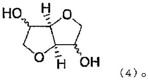
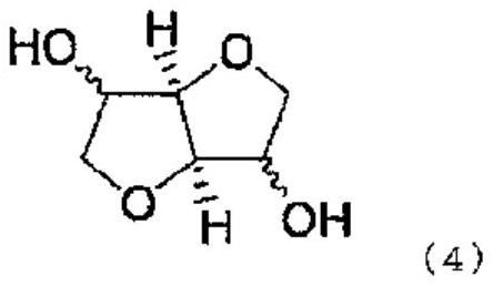
[0122] In a reaction vessel, 47.19 parts by mass of tricyclodecane dimethanol (abbreviated as "TCDDM" below) and 81.98 parts by mass of isosorbide (hereinafter sometimes abbreviated as "ISB"), diphenyl carbonate (hereinafter sometimes abbreviated as Abbreviated as "DPC") 175.1 parts by mass and 0.979 parts by mass of cesium carbonate 0.2 mass % aqueous solution as a catalyst, under a nitrogen atmosphere, as the first stage of the reaction, heat the temperature of the heating tank to 150 ° C, stirring as needed While allowing the ingredients to dissolve (approximately 15 minutes). Next, the pressure was increased from normal pressure to 13.3 kPa, and the temperature of the heating tank was raised to 190° C. over 1 hour, and the generated phenol was taken out of the reaction container. After keeping the entire reaction vessel at 190°C for 15 minutes, as a second-stage process, set the pressure in the reaction vessel to 6.67kPa, raise the te...

Embodiment 2

[0141] Except having set thickness to 30 micrometers, it carried out similarly to Example 1, and obtained the retardation film. The obtained retardation film had an orientation degree of 31.9%, an in-plane retardation Re(550) of 140 nm, and a retardation change rate of 1.15% under humidification. Furthermore, the obtained retardation film was used similarly to Example 1, and the polarizing plate with a retardation layer was obtained. The obtained retardation film and polarizing plate with a retardation layer were subjected to the same evaluation as in Example 1. The results are shown in Table 1.

Embodiment 3

[0143] A retardation film was obtained in the same manner as in Example 1 except that the birefringence Δnxy of the polycarbonate resin was 0.018, the preheating temperature was 138°C, and the stretching temperature was 135°C. The obtained retardation film had an orientation degree of 35.7%, an in-plane retardation Re(550) of 270 nm, and a retardation change rate of 1.29% under humidification. Furthermore, the obtained retardation film was used similarly to Example 1, and the polarizing plate with a retardation layer was obtained. The obtained retardation film and polarizing plate with a retardation layer were subjected to the same evaluation as in Example 1. The results are shown in Table 1.


PUM

PropertyMeasurementUnit
thicknessaaaaaaaaaa
photoelasticityaaaaaaaaaa
thicknessaaaaaaaaaa

Abstract

The invention provides a phase difference film, a polarizing plate with a phase difference layer, and a method for manufacturing the phase difference film. Provided are: a phase difference film which suppresses a change in phase difference in a humidification reliability test, suppresses a change in hue in a weather resistance test in an ultraviolet region, and has excellent adhesiveness; and a polarizing plate with a phase difference layer, which includes the phase difference film. The phase difference film is composed of a resin having birefringence in a predetermined range and has a degree of orientation of 30% or more.

Description

technical field [0001] The invention relates to a retardation film, a polarizing plate with a retardation layer and a manufacturing method of the retardation film. Background technique [0002] In the display market in recent years, there is a need to reduce the brightness of the display in order to prolong the endurance time of the battery and suppress heat generation. Therefore, as a polarizing plate used for a display, a polarizing plate with high light transmittance is required. However, when such a polarizing plate with high light transmittance is used for a display, there is a problem that the appearance deteriorates under humidified conditions. [0003] Furthermore, in recent years, displays have been increasingly used in environments exposed to ultraviolet light (such as PID (public information display), mobile phones), especially for polarizers with a retardation film arranged on the panel side, there is a risk of phase loss due to ultraviolet light. The color cha...

Claims


Application Information

Patent Timeline
Patent Type & Authority Applications(China)
IPC IPC(8): C08J5/18C08L69/00B29C55/16G02B5/30
CPCC08J5/18B29C55/16G02B5/3083C08J2369/00G02B1/04G02B5/3033B29D11/00644C08G64/302C08G64/305
Inventor 中原步梦
Owner NITTO DENKO CORP
Why Eureka
Try Eureka