
Strip-shaped back bolt anchoring structure, stone back bolt anchoring system and anchoring method

An anchoring structure and anchoring system technology, which is applied in the direction of building components, building structures, covering/lining, etc., can solve the problems of small shear surface and unreliable anchoring, and achieve the effects of avoiding failure, facilitating processing quality, and convenient processing

Pending Publication Date: 2022-03-25
CHINA SOUTHWEST ARCHITECTURAL DESIGN & RES INST CORP LTD
View PDF0 Cites 1 Cited by
  • Summary
  • Abstract
  • Description
  • Claims
  • Application Information

AI Technical Summary

Problems solved by technology

[0004] The technical problem to be solved by the present invention is that there are problems such as the small shear surface and unreliable anchoring of the anchorage pendant and stone in the existing inverted tapered back bolt hole structure. The force makes the expansion part expand outward so that it can be stuck into the groove of the stone processing, so as to realize the anchorage of the pendant and the stone

Method used


Image

  • Strip-shaped back bolt anchoring structure, stone back bolt anchoring system and anchoring method
  • Strip-shaped back bolt anchoring structure, stone back bolt anchoring system and anchoring method
  • Strip-shaped back bolt anchoring structure, stone back bolt anchoring system and anchoring method

Examples


Embodiment 1

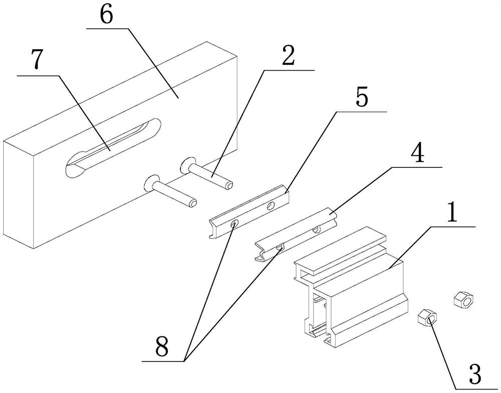
[0036] like figure 1 As shown, a backbolt anchoring structure provided by the embodiment of the present invention includes a strip-shaped support 5 and an expansion member 4; the expansion 5 is used to be arranged between the support 4 and the hanger 1, and the expansion Part 4 can produce outward expansion deformation in width when receiving the clamping force of support part 5 and pendant 2; both support part 5 and expansion part 4 are provided with screw holes 8, and screws 2 pass through the screw holes of the support part in turn , the screw hole of the expansion piece and the screw hole of the pendant are connected with the nut 3 .

[0037] In the back bolt structure of the present invention, when the expansion part is subjected to clamping force, it can produce outward expansion deformation so that it can be stuck in the groove processed by the stone. Compared with the existing anchor structure of the back bolt and the inverted cone back bolt hole, the stone material T...

Embodiment 2

[0041] like figure 1 As shown, a strip-shaped backbolt anchoring structure provided by the embodiment of the present invention includes a strip-shaped support 5 and an expansion piece 4; the expansion piece 5 is used to be arranged between the support 4 and the hanger 1, so The side of the expansion element close to the support element has a slot, and the width of the support element gradually increases along the direction away from the expansion element. The support element can be inserted into the slot to expand the expansion element in the width direction. Specifically, The cross section of the expansion part is "M" shape; the support part 5, the expansion part 4 and the hanging part 1 are provided with two screw holes 8 along the length direction, and the screws 2 pass through the screw holes of the support part, the expansion part and the The screw holes of the pendant 1 and the screw holes of the pendant 1 are connected with the nut 3.

[0042] In the anchoring structur...

Embodiment 3

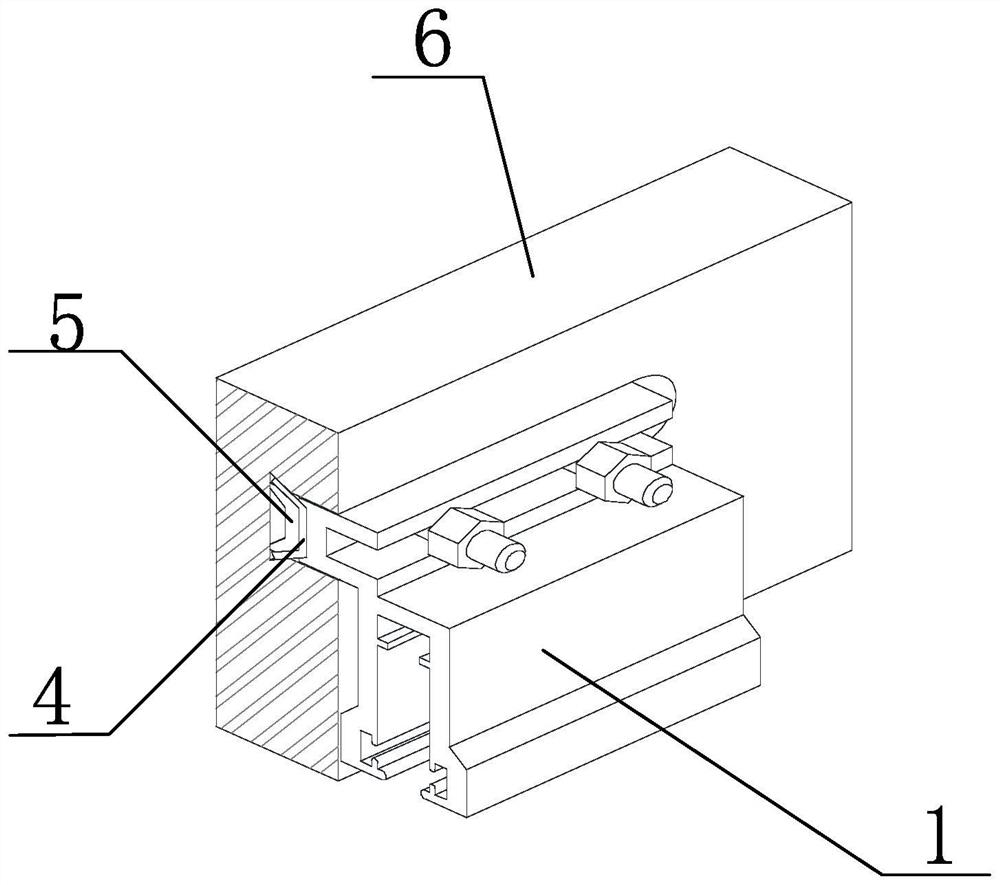
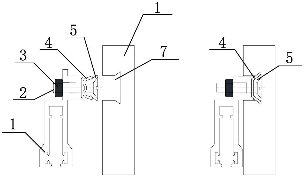
[0046] like Figure 1-3 As shown, a strip-shaped stone back bolt anchoring system provided by the embodiment of the present invention includes stone 6, support 5, expansion 4 and aluminum alloy pendant 1, a strip-shaped dovetail groove 7 is opened on the back of the stone, and the support 5 , the expansion part 4 and the pendant 1 are provided with screw holes 8, and the screws 2 pass through the screw holes of the support part 5, the screw holes of the expansion part 4 and the screw holes of the pendant 1 in order to connect with the nut 3, and the support part 5 and the expansion part 4 is set in the dovetail groove 7, and the aluminum alloy pendant 1 and the support piece 5 clamp the expansion member 4 by tightening the nut 2, and the edges on both sides of the expansion member 4 expand outward in the width direction and snap into the dovetail groove 7.

[0047] The present invention adopts the external expansion structure of the dovetail groove and the expansion part of th...


PUM


Abstract

The strip-shaped back bolt anchoring structure comprises a stone, a supporting piece, an expansion piece and a hanging piece, a strip-shaped dovetail groove is formed in the side wall of the stone, and screw holes are formed in the supporting piece, the expansion piece and the hanging piece; the screw sequentially penetrates through the screw hole of the supporting piece, the screw hole of the expansion piece and the screw hole of the hanging piece to be connected with the nut, the supporting piece and the expansion piece are arranged in the dovetail groove, and the aluminum alloy hanging piece and the supporting piece clamp the expansion piece in the width direction and expand outwards to be clamped into the dovetail groove by screwing the nut. Anchoring of the aluminum alloy hanging piece and the stone plate is achieved through the dovetail groove and back bolt expansion piece external expansion structure, firstly, the dovetail groove is convenient to machine and reliable in quality, the machined dovetail groove is convenient to detect, and the machining quality of the groove can be conveniently controlled; the dovetail groove of the strip-shaped structure and the strip-shaped back bolt are combined for use, so that the shear surface of the stone is larger, the stress is better, and meanwhile, the hanging piece and the stone cannot rotate after being connected.

Description

technical field [0001] The invention relates to the technical field of back bolt anchoring for stone curtain walls, in particular to a strip-shaped back bolt anchoring structure, a stone back bolt anchoring system and an anchoring method. Background technique [0002] The existing stone curtain wall back-bolt anchorage system has the following problems: 1. The back-bolt hole is an inverted cone hole with a special processing method, and the processing quality of the back-bolt hole is difficult to control. At the same time, there is no reliable detection method after the back-bolt hole is processed; 2. The force on the stone plate at the position where the back bolt is connected to the stone is that the stone is sheared around the back bolt hole, and the length of the sheared surface of the stone is relatively short; The installation is unreliable; 4. The back bolt hole on the stone is small. If there is a loose hole in the stone where the back bolt hole is processed, it may ...

Claims


Application Information

Patent Timeline
Patent Type & Authority Applications(China)
IPC IPC(8): E04B2/88E04F13/22
CPCE04B2/88E04F13/081
Inventor 罗建成董彪钱方李涛高冬冬
Owner CHINA SOUTHWEST ARCHITECTURAL DESIGN & RES INST CORP LTD
Learn More