
Laser printer with reverse paper feeding correction device

A laser printer and correction device technology, which is applied in optics, electrical recording process applying charge pattern, equipment for electrical recording process applying charge pattern, etc. Installation, poor printing quality and other problems, to achieve accurate calibration, ensure the printing effect, and avoid the effect of gaps

Pending Publication Date: 2022-03-25
HUNAN GREATWALL INFORMATION FINANCIAL EQUIP
View PDF0 Cites 0 Cited by
  • Summary
  • Abstract
  • Description
  • Claims
  • Application Information

AI Technical Summary

Problems solved by technology

[0004] In order to overcome the above-mentioned defects of the prior art, an embodiment of the present invention provides a laser printer with a paper-traversing correction device on the reverse side. When printing the reverse side, this often causes problems such as the paper and the printer's paper inlet are not perpendicular, the paper is skewed, and the print quality is poor

Method used


Image

  • Laser printer with reverse paper feeding correction device
  • Laser printer with reverse paper feeding correction device
  • Laser printer with reverse paper feeding correction device

Examples


Embodiment Construction

[0027] The present invention will be described in detail below in conjunction with the accompanying drawings.

[0028] The following will clearly and completely describe the technical solutions in the embodiments of the present invention with reference to the accompanying drawings in the embodiments of the present invention. Obviously, the described embodiments are only some, not all, embodiments of the present invention. Based on the embodiments of the present invention, all other embodiments obtained by persons of ordinary skill in the art without making creative efforts belong to the protection scope of the present invention.

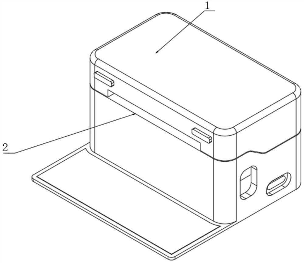
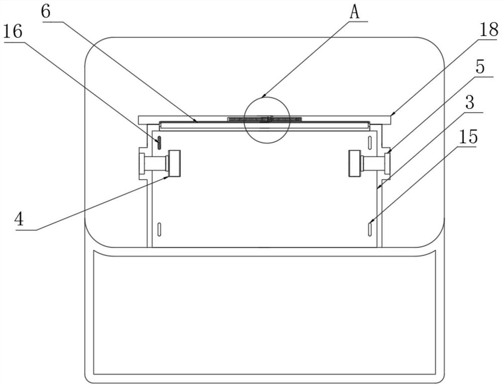
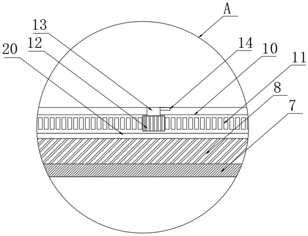
[0029] Such as Figure 1-5 As shown, this embodiment provides a laser printer with a backside paper feeding correction device, including a printer body 1, a print slot 2 located on one side of the printer body 1, and a correction assembly arranged in the print slot 2; the correction The assembly includes a correction plate 3, correction wheels 4 loc...


PUM


Abstract

The invention discloses a laser printer with a reverse paper feeding correction device. The laser printer comprises a printer body, a printing groove and a correction assembly. The correction assembly comprises a correction plate, a correction wheel and a clamping assembly, correction grooves are symmetrically formed in the two sides of the correction plate in the length direction, and induction assemblies are correspondingly arranged at the bottoms of the correction grooves; the clamping assembly comprises a clamping base, a driving base fixed to the side, away from the correcting plate, of the clamping base, a vertical plate fixed to the top of the clamping base, a clamping plate assembled with the vertical plate in an up-down sliding mode and a spring used for sliding reset of the clamping plate, an electromagnetic adsorption block is arranged in the clamping base, and a magnetic coating is arranged on the clamping plate. A rack is arranged at the top of the driving seat, and the top of the rack is meshed with a gear driven by a motor; the induction assembly is electrically connected with the motor. According to the laser printer, paper feeding correction is achieved, and the printing quality is improved.

Description

technical field [0001] The invention relates to the technical field of laser printers, in particular to a laser printer with a reverse paper feeding correction device. Background technique [0002] Laser printers originated from the laser phototypesetting technology in the late 1980s and became popular in the mid-1990s. It is a print output device that combines laser scanning technology and electrophotography technology. Its basic working principle is that the binary data information sent by the computer is converted into a video signal by the video controller, and then the video signal is converted into a laser driving signal by the video interface / control system, and then the laser scanning system generates the character information. The laser beam is finally imaged by an electrophotographic system and transferred to paper. Compared with other printing devices, laser printers have the advantages of fast printing speed and high image quality. [0003] In the prior art, t...

Claims


Application Information

Patent Timeline
Patent Type & Authority Applications(China)
IPC IPC(8): G03G15/00
CPCG03G15/6529G03G15/6567G03G15/6579
Inventor 古志超崔冬旭
Owner HUNAN GREATWALL INFORMATION FINANCIAL EQUIP
Learn More