Electrical cabinet with slidable turnover type mounting plate

A technology for mounting boards and electrical cabinets, applied in the field of electrical cabinets, can solve the problems that the mounting board equipment cannot be installed more flexibly, cannot be moved and turned, and cannot be adjusted in the angle of the mounting board, etc. The effect of improving the heat dissipation effect

Pending Publication Date: 2022-03-25
XIAN TECHNOLOGICAL UNIV
View PDF0 Cites 0 Cited by
  • Summary
  • Abstract
  • Description
  • Claims
  • Application Information

AI Technical Summary

Problems solved by technology

[0004] The object of the present invention is to provide an electrical cabinet with a slidable flip-up mounting plate, aiming at solving the problem that in the prior art, the internal partitions or mounting plates of the electrical cabinet are mostly fixed mounting plates fastened by bolts, because the mounting plate is fixed It is very inconvenient when the angle of the mounting plate cannot be adjusted and the parts installed on the mounting plate need to be repaired, and the equipment on the mounting plate cannot be installed more flexibly. Moreover, the external layout of most existing electrical cabinets is rectangular, and this structure does not take advantage of the heat dissipation of internal equipment and other issues.

Method used


Image

  • Electrical cabinet with slidable turnover type mounting plate
  • Electrical cabinet with slidable turnover type mounting plate
  • Electrical cabinet with slidable turnover type mounting plate

Examples


Embodiment 1

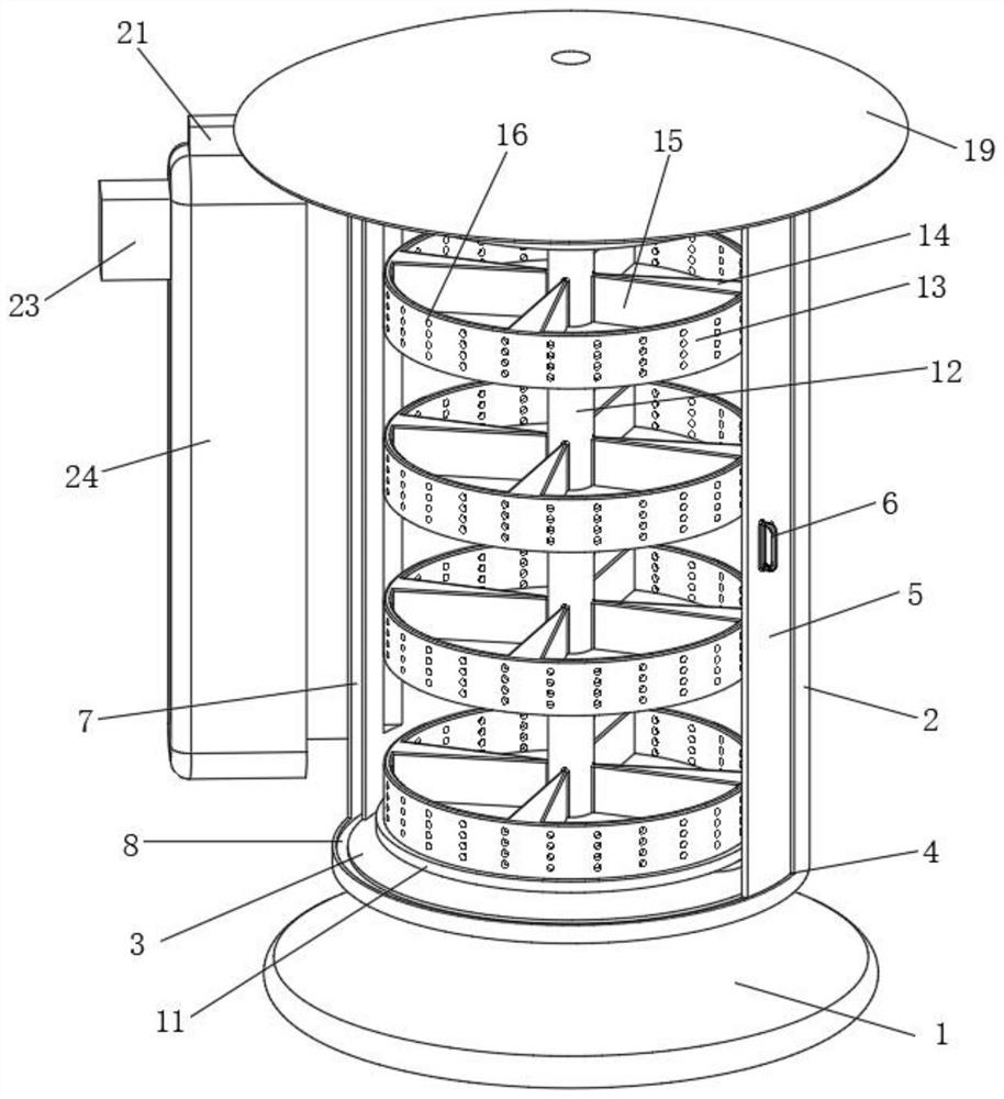
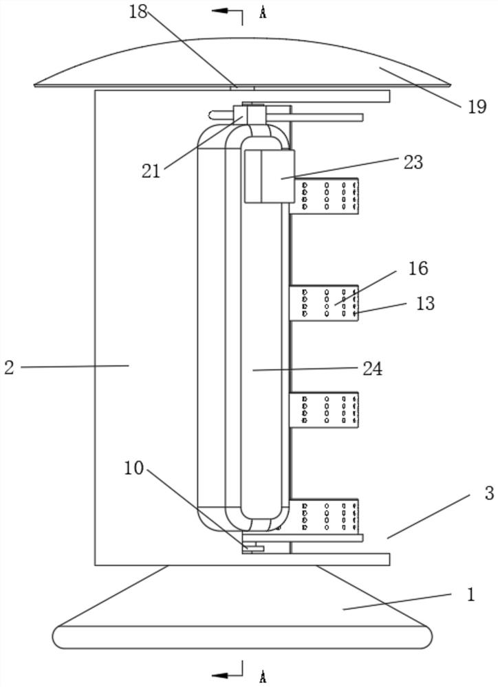
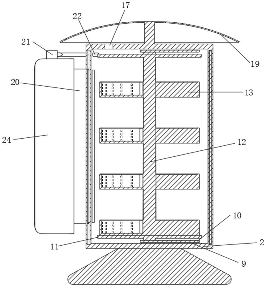
[0028] see Figure 1-Figure 5 , the present invention provides the following technical solutions: an electrical cabinet with a slidable flip-up mounting plate includes a cabinet body 2, a sliding door mechanism is arranged on the front side of the cabinet body 2, and a connecting shaft 12 is connected to the inside of the cabinet body 2 through a flip mechanism, The connecting shaft 12 is provided with multiple sets of equidistant placement mechanisms, the side wall of the cabinet body 2 is provided with a heat dissipation mechanism, and the turning mechanism includes two hinge shafts 9, and the two hinge shafts 9 are respectively rotatably connected to the upper and lower sides of the cabinet body 2. On the inner wall, the two hinge shafts 9 are rotatably connected to an overturning plate 10 at one end close to each other;

[0029]In a specific embodiment of the present invention, the entire electrical cabinet has a reasonable structure, ingenious conception, flexible use, co...


PUM


Abstract

The invention provides an electrical cabinet with a slidable turnover type mounting plate, and belongs to the technical field of electrical cabinets, the electrical cabinet with the slidable turnover type mounting plate comprises a cabinet body, the front side of the cabinet body is provided with a sliding door mechanism, the cabinet body is internally connected with a connecting shaft through a turnover mechanism, and the connecting shaft is provided with a plurality of groups of placing mechanisms which are distributed at equal intervals; a heat dissipation mechanism is arranged on the side wall of the cabinet body, the turnover mechanism comprises two hinged shafts, the two hinged shafts are rotationally connected to the upper inner wall and the lower inner wall of the cabinet body respectively, the ends, close to each other, of the two hinged shafts are rotationally connected with turnover plates, the whole electrical cabinet is reasonable in structural arrangement, ingenious in conception and flexible to use, equipment in the cabinet body is convenient to assemble and disassemble, the maintenance cost is reduced, and the service life of the electrical cabinet is prolonged. Meanwhile, an existing rectangular cabinet body is changed into a columnar structure, heat generated by equipment in the cabinet body can be conveniently dissipated in cooperation with a heat dissipation mechanism, the heat dissipation effect is improved, meanwhile, the machining cost is reduced, and high practicability is achieved.

Description

technical field [0001] The invention belongs to the technical field of electrical cabinets, and in particular relates to an electrical cabinet with a slidable and reversible mounting plate. Background technique [0002] The electrical cabinet is a cabinet made of steel to protect the normal operation of components. The material of the electrical cabinet is generally divided into two types: hot-rolled steel plate and cold-rolled steel plate. Compared with hot-rolled steel plate, cold-rolled steel plate is softer and more suitable for electrical cabinets. Production, electrical cabinets are widely used mainly in chemical industry, environmental protection industry, power system, metallurgical system, industry, nuclear power industry, fire safety monitoring, transportation industry and so on. [0003] At present, most of the partitions or mounting plates in the existing electrical cabinet are fixed mounting plates fastened by bolts. Since the mounting plate is fixed, it cannot ...

Claims


Application Information

Patent Timeline
Patent Type & Authority Applications(China)
IPC IPC(8): H05K5/02H05K5/06H05K7/14H05K7/20
CPCH05K5/0217H05K5/0226H05K5/023H05K5/061H05K7/1422H05K7/20145H05K7/20136
Inventor 徐小慧霍文俊
Owner XIAN TECHNOLOGICAL UNIV
Why Eureka
Try Eureka