Batching machine for thermal insulation production of rock wool

A technology of batching machine and rock wool, applied in the field of batching machine for rock wool thermal insulation production, can solve the problems of low mixing degree, low efficiency, bloated mechanism, etc., and achieve the effect of smooth mixing, high efficiency and simplified mechanism

Inactive Publication Date: 2022-03-29
安庆市大成防腐保温材料有限责任公司
View PDF0 Cites 0 Cited by
  • Summary
  • Abstract
  • Description
  • Claims
  • Application Information

AI Technical Summary

Problems solved by technology

[0004] The purpose of the present invention is to solve the problems of low mixing degree, bloated mechanism and low efficiency in the prior art, and propose a batching machine for rock wool insulation production

Method used


Image

  • Batching machine for thermal insulation production of rock wool
  • Batching machine for thermal insulation production of rock wool
  • Batching machine for thermal insulation production of rock wool

Examples


Embodiment 1

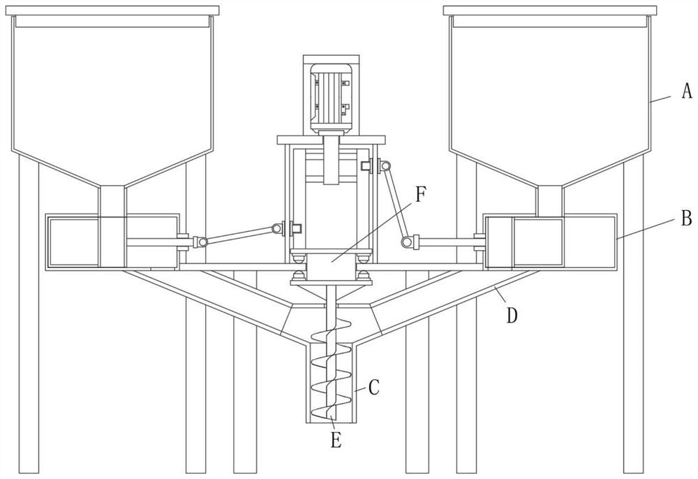
[0028] refer to Figure 1-4 , a batching machine for rock wool insulation production, including a raw material bin A and a centralized discharge pipe C, there are multiple raw material bins A, and the bottom of the raw material bin A is provided with a feeding mechanism B, and the bottom of the feeding mechanism B is connected to the centralized The discharge pipes C are fixedly connected with the feed pipe D, and the top of the concentrated discharge pipe C is divergently provided with connection holes. The central discharge pipe C is vertically rotated and installed with a spiral discharge shaft E. Between each raw material warehouse A There is a linkage mechanism F that drives each reclaiming mechanism B to run synchronously. The linkage mechanism F drives the reclaiming mechanism B, and the raw materials in each raw material bin A are introduced into the discharge pipe C through the guide pipe D at intervals. The screw discharge shaft E in the discharge pipe C also rotates...

Embodiment 2

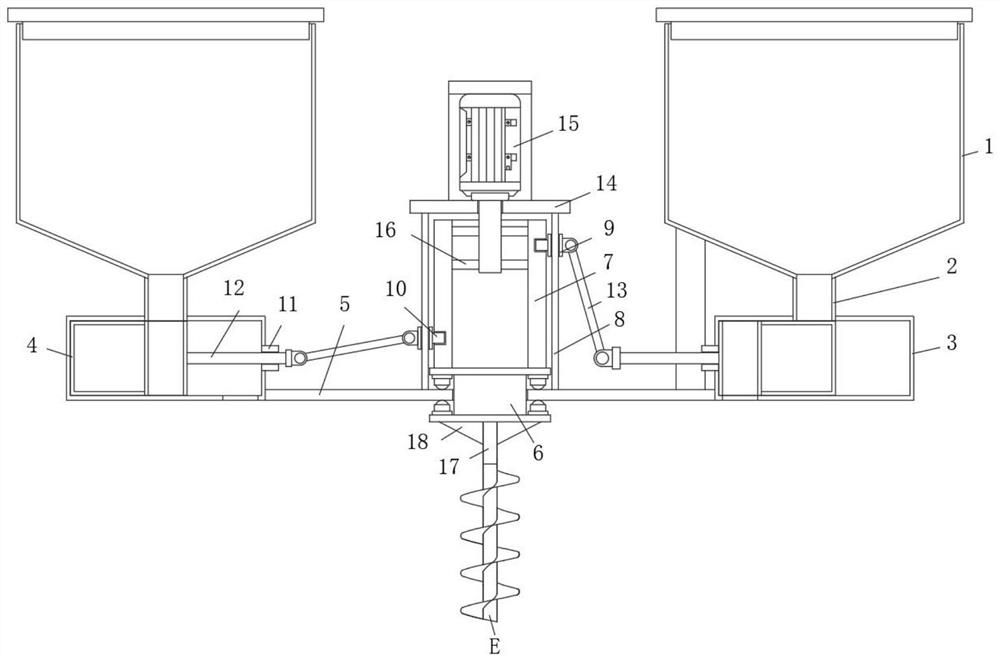
[0033] like Figure 1-4 As shown, this embodiment is basically the same as Embodiment 1. Preferably, the screw discharge shaft E is located in the centralized discharge pipe C, and the top of the screw discharge shaft E is coaxially fixedly connected with an oblong shaft 17, and the oblong shaft 17 The top end passes through the top of the centralized discharge pipe C and is coaxially fixedly connected with the bottom side of the turntable 6 , and a reinforcing rib 18 is provided between the long circular axis 17 and the turntable 6 .

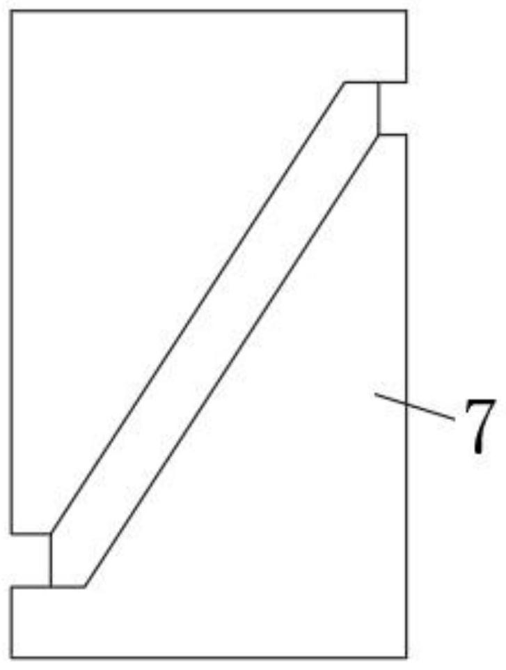
[0034] In this embodiment, through the setting of the oblong shaft 17, it is possible to drive the screw discharge shaft through the turntable 6 and the oblong shaft 17 to concentrate the discharge pipe C while driving the rotating drum 7 to rotate and carry out the interval blanking of the material. The internal rotation ensures the smoothness of blanking.

Embodiment 3

[0036] like Figure 1-4 As shown, this embodiment is basically the same as Embodiment 1. Preferably, the top of the track pole 8 is fixedly connected with a top platform 14, and a motor 15 is fixedly installed on the top platform 14, and the output shaft of the motor 15 extends to the drive shaft. The inner side of the cylinder 7 is fixedly connected with the inner wall of the driving drum 7 with several umbrella shafts 16 arranged in a divergent manner.

[0037] In this embodiment, the umbrella shaft 16 outside the output shaft of the motor 15 drives the entire drive drum 7 to rotate, and the turntable 6 and the oblong shaft 17 at the bottom of the drive drum 7 also rotate accordingly.


PUM


Abstract

The invention discloses a batching machine for rock wool thermal insulation production, the batching machine comprises a plurality of raw material bins and a centralized discharge pipe, the bottom of each raw material bin is provided with a material taking mechanism, a material guide pipe is fixedly communicated between the bottom of each material taking mechanism and the centralized discharge pipe, and the top of the centralized discharge pipe is provided with connecting holes in a divergent manner. A spiral discharging shaft is vertically and rotatably mounted in the centralized discharging pipe, and linkage mechanisms for driving all the material taking mechanisms to synchronously run are arranged among all the raw material bins; the raw material bin comprises a raw material storage barrel and a discharging square pipe fixedly communicated to the bottom of the raw material storage barrel, the material taking mechanism comprises a material blocking enclosure fixedly arranged on the outer side of the bottom end of the discharging square pipe in a sleeving mode, and the material blocking enclosure is of a rectangular box structure. In the batching process, mixing of various materials is completed, the material mixing is smooth, the effect is good, meanwhile, the design is reasonable, the mechanism is simple, the linkage performance is high, and the use requirements of people in production and life are met.

Description

technical field [0001] The invention relates to the technical field of rock wool insulation board production equipment, in particular to a batching machine for rock wool insulation production. Background technique [0002] The rock wool insulation board is made of basalt and other natural ores as the main raw materials. After melting, the international advanced four-roller centrifugal cotton-making process is adopted to pull the basalt rock high-temperature melt into 4-7μm discontinuous fibers, and then Add a certain amount of binder, dustproof oil, and water repellent to the rock wool fiber, and after sedimentation, curing, cutting and other processes, a series of products with different densities are made according to different uses. Rock wool insulation board products are suitable for thermal insulation and sound insulation of industrial equipment, buildings and ships. [0003] In the production process of the existing rock wool materials, according to the use and enviro...

Claims


Application Information

Patent Timeline
Patent Type & Authority Applications(China)
IPC IPC(8): B29B7/24B29B7/88
CPCB29B7/24B29B7/88
Inventor 王云伍方勇刘友华
Owner 安庆市大成防腐保温材料有限责任公司
Why Eureka
Try Eureka