
Automatic sampler

An automatic sampler and sample technology, which is applied in sampling, sampling devices, instruments, etc., can solve the problems that the authenticity of samples cannot be guaranteed, samples are distorted, and samples cannot be obtained.

Pending Publication Date: 2022-03-29
MUYUAN FOODS CO LTD
View PDF0 Cites 0 Cited by
  • Summary
  • Abstract
  • Description
  • Claims
  • Application Information

AI Technical Summary

Problems solved by technology

However, in the grain or feed processing production line, there will be great differences in the feed particles sliding in the chute, especially the feed flow in the chute will cause feed grading during the sliding process of the feed along the chute, resulting in fine powder particles It will sink from the gap of large particles to the bottom of the chute with the material flow along the chute, so that part of the feed that is close to the wall of the chute is powder, and its particle size is relatively fine. The feed particles in the upper part are larger
Under the above circumstances, when sampling with the above sampler, the stroke of the cylinder should not be too large, otherwise the chute will be blocked. Non-mixed feed samples with better uniformity, this sample cannot truly represent the uniform distribution of the overall feed particles, resulting in sample distortion
In addition to the feed grading phenomenon, there is also the situation that the feed remains at the bottom of the chute, causing the feed that continuously enters the chute to move over the residual material and move from the inner side wall of the chute. In this case, it is impossible to get a real sample
Furthermore, when there is less feed in the chute, the amount of feed at the bottom of the chute is thinner, and the authenticity of the samples taken during the flow of the feed cannot be guaranteed when the material is relatively thin.

Method used


Image

  • Automatic sampler

Examples


Embodiment Construction

[0033] The technical terms or scientific terms used in this specification should have the usual meanings understood by those skilled in the art: "first", "second" and similar words used in this specification do not indicate any order, quantity or importance, and are only used to distinguish different components; words such as "connect" or "communication" are not limited to physical or mechanical connections, but may include various forms of connections, whether direct or indirect; ", "Down", "Left", "Right", "Front", "Back", "Far", "Near", "Start", "End", etc. After the absolute position of the relative position changes, the relative positional relationship may also change accordingly; in addition, in the description of this specification, unless otherwise specified, the meanings of "multiple" and "several" are two or more.

[0034] In order to better understand the present invention, the embodiments of the present invention will be described below in conjunction with the acco...


PUM


Abstract

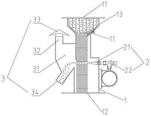
The invention relates to the technical field of feed processing equipment, in particular to an automatic sampler which comprises a tubular body, the tubular body is provided with a first connecting end for feeding and a second connecting end for discharging, a blowing part and a sample receiving part which are communicated with the tubular body are arranged on the two sides of the tubular body respectively, and the blowing part and the sample receiving part are oppositely arranged. And a nozzle of the blowing part faces the sample receiving part, so that when the feed flows from the first connecting end to the second connecting end, the nozzle makes the blown feed enter the sample receiving part at the moment of blowing the feed. According to the device, the blowing part and the sample receiving part which are arranged on the two sides of the tubular body are matched with each other for sampling, and the original mixing uniformity of feed is not influenced due to the movement of the feed in the vertical direction in the sampling process, so that any part of a feed column formed in the falling process of the feed is sampled; and the feed particles with different particle sizes can be blown into the sample receiving part by the blowing airflow, so that the authenticity of the obtained sample is ensured, and the obtained sample is more representative.

Description

technical field [0001] The invention relates to the technical field of feed processing equipment, in particular to an automatic sampler. Background technique [0002] In the production process of continuous operations such as grain and feed production and processing, most of the equipment on the production line is airtight, but in order to control the production status of each link of the production line, it is often necessary to use a sampler to achieve it, that is, in feed production. A sampler is required for each process. The sampler is divided into automatic and manual. The manual sampler needs to manually open the sampling port, insert the sampler into the sampling port for sampling, and then close the sampling port after the sampling work is completed. The disadvantage of manual sampling operation is that the sampling operation must be carried out on site. The sampling work is very inconvenient; the automatic sampler uses the controller to control the sampling actuat...

Claims


Application Information

Patent Timeline
IPC IPC(8): G01N1/20
CPCG01N1/2035
Inventor 褚柯曲东阁何佳珊吴珂
Owner MUYUAN FOODS CO LTD
Learn More