Loudspeaker and electronic equipment

A loudspeaker and center technology, which is applied to the transducer shell/cabinet/support, sensor, electrical components, etc., can solve the problem of reducing the frequency response of the moving coil electro-acoustic converter, reducing the effective vibration and sound area of ​​the diaphragm, and reducing the loudspeaker. The performance is difficult to improve and other problems, to achieve the effect of increasing the effective vibration space, the vibration amplitude is large, and the space occupied is small

Pending Publication Date: 2022-03-29
GOERTEK INC
View PDF0 Cites 0 Cited by
  • Summary
  • Abstract
  • Description
  • Claims
  • Application Information

AI Technical Summary

Problems solved by technology

Therefore, after removing various main components such as chips, batteries, motherboards, and motors, there is very little space left for the built-in speakers, and it is difficult to improve the performance of the speakers.
[0004] And the effective vibration and sound part of the diaphragm is actually the rigid part of the center, and the flexible ring part on the edge occupies a large amount of dimensional space. In the case of continuous shrinking of product size, especially when the width of the product is reduced, The effective vibration sound area of ​​the diaphragm is greatly reduced, which will result in a decrease in the frequency response of the dynamic electro-acoustic transducer

Method used


Image

  • Loudspeaker and electronic equipment
  • Loudspeaker and electronic equipment
  • Loudspeaker and electronic equipment

Examples


Embodiment Construction

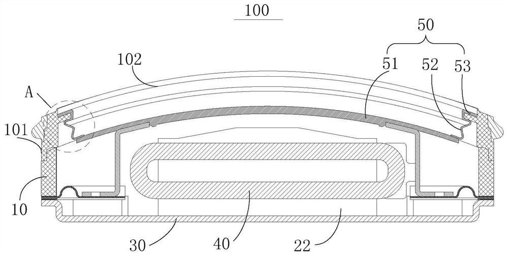
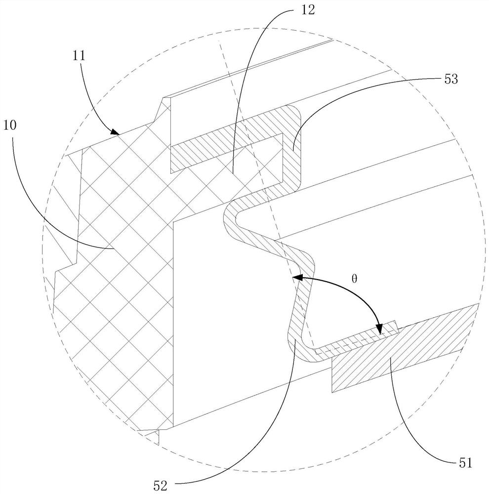
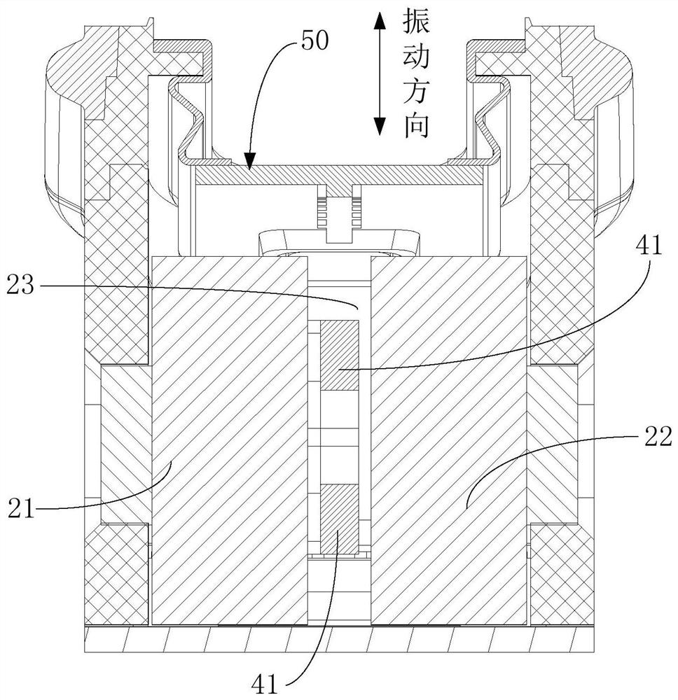
[0034] The following will clearly and completely describe the technical solutions in the embodiments of the present invention with reference to the accompanying drawings in the embodiments of the present invention. Obviously, the described embodiments are only some of the embodiments of the present invention, not all of them. Based on the embodiments of the present invention, all other embodiments obtained by persons of ordinary skill in the art without creative efforts fall within the protection scope of the present invention.

[0035] It should be noted that if there are directional indications involved in the embodiment of the present invention, the directional indications are only used to explain the relative positional relationship, movement conditions, etc. between the components in a specific posture. If the specific posture changes , then the directional indication changes accordingly.

[0036] In addition, if there are descriptions involving "first", "second" and so o...


PUM


Abstract

The invention discloses a loudspeaker and electronic equipment. The loudspeaker comprises a shell, a magnetic circuit system and a vibration system, the magnetic circuit system comprises a first magnet part and a second magnet part which are arranged at intervals to form a magnetic gap, a first magnetic gap is formed between two opposite opposite magnetic poles at the upper parts of the first magnet part and the second magnet part, and a second magnetic gap is formed between two opposite opposite magnetic poles at the lower parts of the first magnet part and the second magnet part; the magnetic pole distribution directions of the two opposite opposite magnetic poles at the upper part and the two opposite opposite magnetic poles at the lower part are opposite; the vibration system comprises a vibrating diaphragm and a flat voice coil for driving the vibrating diaphragm to vibrate; the vibrating diaphragm comprises a central part, a folding ring part which is annularly arranged on the peripheral side of the central part, and an edge part which is annularly arranged on the peripheral side of the folding ring part; the central part is in a bent shape and protrudes towards the direction far away from the flat voice coil; the folding ring part is connected with the edge of the central part, and bends and extends towards the vibration direction of the vibrating diaphragm; the edge portion is connected to the housing. According to the invention, the loudspeaker has a small size and good acoustic performance.

Description

technical field [0001] The invention relates to the technical field of sound energy conversion, in particular to a loudspeaker and electronic equipment. Background technique [0002] For dynamic speakers, their acoustic performance is directly related to their size. The larger the size, the better the acoustic effect, and the smaller the size, the worse the acoustic effect. [0003] Due to the consideration of portability, comfort, and aesthetics, electronic devices, such as mobile phones or wearable smart terminals, have relatively strict size requirements, and the size and thickness tend to be miniaturized. Therefore, after removing various main components such as chips, batteries, motherboards, and motors, the space left for the built-in speakers is very small, and it is difficult to improve the performance of the speakers. [0004] And the effective vibration and sound part of the diaphragm is actually the rigid part of the center, and the flexible ring part on the edg...

Claims


Application Information

Patent Timeline
Patent Type & Authority Applications(China)
IPC IPC(8): H04R1/02H04R7/02H04R9/02H04R9/04
CPCH04R1/02H04R9/025H04R9/04H04R7/02
Inventor 蔡晓东张琳琳刘春发
Owner GOERTEK INC
Why Eureka
Try Eureka