
Modularized annular unfolding type container house

A container and unfolding technology, applied to photovoltaic modules, photovoltaic module support structures, roofs, etc., can solve the problems of single style, small use area, and poor thermal insulation performance of container houses, so as to improve external thermal insulation performance, structural shockproof, The effect of less manpower and man-hours

Pending Publication Date: 2022-04-01
张承泽
View PDF0 Cites 0 Cited by
  • Summary
  • Abstract
  • Description
  • Claims
  • Application Information

AI Technical Summary

Problems solved by technology

[0006] The purpose of the present invention is to provide a modular ring-shaped expandable container house, which mainly solves the problem that the usable area inside a single container box is too small in the prior art, and also solves the problem of poor external thermal insulation performance of the container house and no power supply in special areas The problem of single facilities and style

Method used


Image

  • Modularized annular unfolding type container house
  • Modularized annular unfolding type container house
  • Modularized annular unfolding type container house

Examples


Embodiment 1

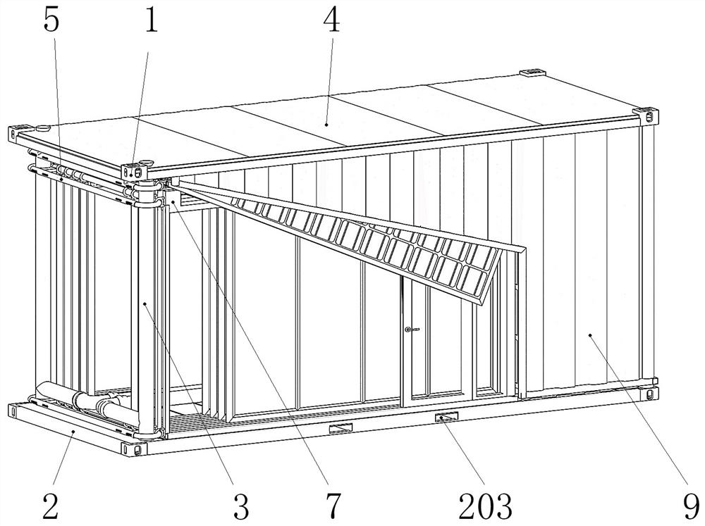
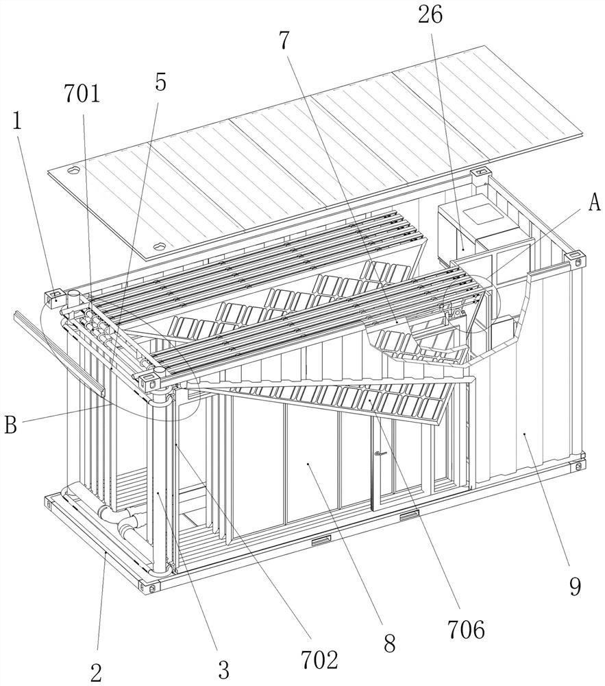
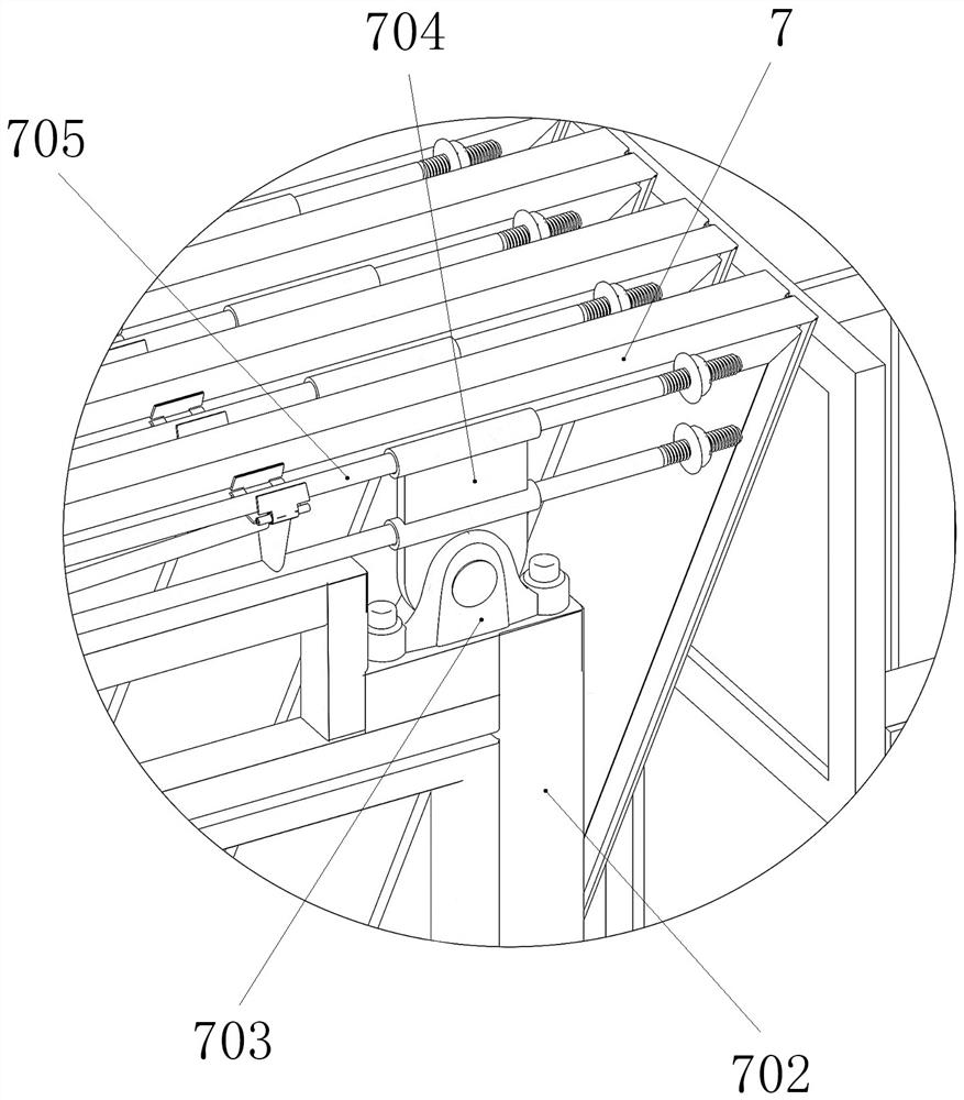
[0046]The modular ring-shaped expandable container house includes a container body and a kitchen and bathroom system. The container body includes an upper frame, corner fittings, corner columns, wall panels, a lower frame, and a forklift port. One end of the container body The two corner columns of the container body are correspondingly arranged on the inner side of the corner piece 1; the four corner columns of the container box are slidingly fitted lifting columns 3, and the lifting columns are composed of an inner tube column and an outer tube set on the inner tube column 301. Composed of column 302, a lifting limit piece is arranged on the lifting column to realize the limit after the container body is raised; an annular pipe fitting 5 is arranged around the periphery of the two lifting columns located inside the corner fittings, and the annular pipe fitting The lower and upper parts of the outer pipe string and the upper part of the inner pipe string are respectively conne...

Embodiment 2

[0052] On the basis of Example 1, in order to improve the thermal insulation requirements of container houses, a multi-layer air bag thermal insulation structure composed of multiple multi-layer modular thermal insulation air bags 15 is also provided on the inside of the installed house body. Each multi-layer module The thermal insulation airbags are equipped with inflation valve 30 and airbag connecting rope; after the multi-layer modular thermal insulation airbags are spliced ​​with each other through the groove structure inserted into each other, they are fixedly connected by the airbag connecting rope; the multilayer airbag insulation structure is also connected by The airbag connecting rope is fixedly connected with multiple positions inside the room body.

[0053] Ground beams, floors, roof panels, waterproof tiles, waterproof rubber strips, waterproof cover panels, roof panels, roof decorative strips, roof decorative corners, kitchen and bathroom systems, rain pads, mult...


PUM


Abstract

The invention discloses a modularized annular unfolding type container house. Two corner stand columns at one end of a container body are correspondingly arranged on the inner sides of corner fittings; four corner stand columns of the container body are lifting pipe columns which are sleeved in a sliding mode, and lifting limiting pieces are arranged on the lifting pipe columns. Annular pipe fittings are arranged on the peripheries of the two lifting pipe columns located on the inner sides of the corner fittings in a surrounding mode, a plurality of supporting frame units with lantern rings are correspondingly arranged on the two sides of the interior of the container body, and the supporting frame units are connected with the annular pipe fittings in a sliding mode through the lantern rings. Through the lifting corner stand column structures and the annularly-unfolded supporting frame unit structures, the modular annularly-unfolded container house is achieved; the problem that in the technical field of container houses, the internal use area of a single box is small is mainly solved, and meanwhile the problems that the external thermal insulation performance of the container houses is poor, the box building style is single, and power supply is achieved in special areas are solved.

Description

technical field [0001] The invention belongs to container house technology, and in particular relates to a modular ring-shaped expandable container house. Background technique [0002] In order to meet the requirements for mobile houses in various fields, container houses have emerged as the times require, and their advantages are convenient transportation, easy loading and unloading, and shockproof structures. [0003] However, the main problem of the existing container houses is that the internal use area of ​​a single container is too small. The usable area inside the ordinary container house is only 14.4 square meters (the length of the box is 6 meters and the width is 2.4 meters). The usable area can be increased by overlapping multiple container boxes, but this technology increases the transport quantity of the container boxes and increases the transportation cost. Therefore, in the prior art of container houses, how to maximize the internal usable area of ​​the conta...

Claims


Application Information

Patent Timeline
Patent Type & Authority Applications(China)
IPC IPC(8): E04B1/343E04B1/344E04B1/80E04B7/16H02S20/30
CPCY02E10/50
Inventor 张承泽
Owner 张承泽
Learn More