
Erosion-resistant balanced regulating valve

A balanced, regulating valve technology, applied in the direction of lift valve, valve details, valve device, etc., can solve the problems of short valve service life, large erosion damage, poor erosion resistance, etc., to improve control accuracy and adjustment performance, The effect of reducing equipment cost

Pending Publication Date: 2022-04-01
WUXI SCORE AUTOMATIC CONTROL EQUIP CO LTD
View PDF0 Cites 0 Cited by
  • Summary
  • Abstract
  • Description
  • Claims
  • Application Information

AI Technical Summary

Problems solved by technology

In these occasions, the flow rate of the medium at the throttle port of the valve is very high, with great kinetic energy, which can quickly push the valve core and the surface of the valve seat out of the streamline-shaped groove, thereby destroying the sealing surface and causing the valve to fail. or scrapped
Especially when the valve is working at a small opening, the throttling gap is smaller, the fluid velocity is faster, the scouring damage is greater, and the service life of the valve is shorter
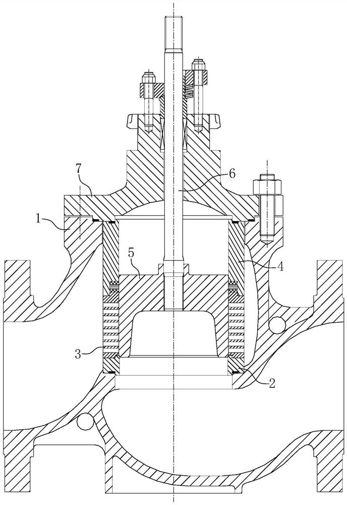
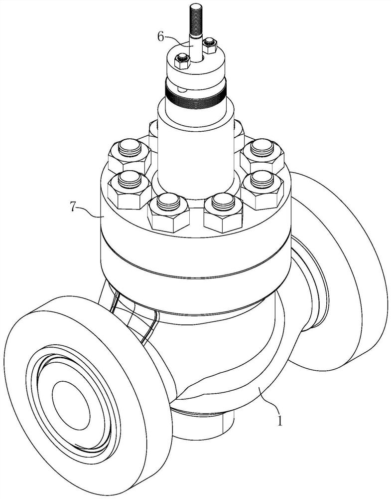
[0004] The structure of the traditional sleeve-type control valve is as attached to the instruction manual. figure 1 As shown, it is composed of valve body 1, valve seat 2, sleeve 3, pressure ring 4, valve core 5, valve stem 6, valve cover 7 and other components. When the pressure difference is alternating, it is necessary to overcome a large unbalanced force, so the structure is limited to the small diameter and low pressure difference occasions. When the pressure difference is alternating, the valve core is prone to shake and the erosion resistance is poor.

Method used


Image

  • Erosion-resistant balanced regulating valve
  • Erosion-resistant balanced regulating valve
  • Erosion-resistant balanced regulating valve

Examples


Embodiment Construction

[0023] The following will clearly and completely describe the technical solutions in the embodiments of the present invention with reference to the accompanying drawings in the embodiments of the present invention. Obviously, the described embodiments are only part of the embodiments of the present invention, not all of them. Based on the embodiments of the present invention, all other embodiments obtained by persons of ordinary skill in the art without creative efforts fall within the protection scope of the present invention.

[0024] It should be noted that if there are directional indications such as up, down, left, right, front, back, etc. in the embodiment of the present invention, the directional indications are only used to explain the position of each individual in a certain posture as shown in the attached figure. If the relative positional relationship, movement conditions, etc. between the components change, the directional indication will also change accordingly. ...


PUM


Abstract

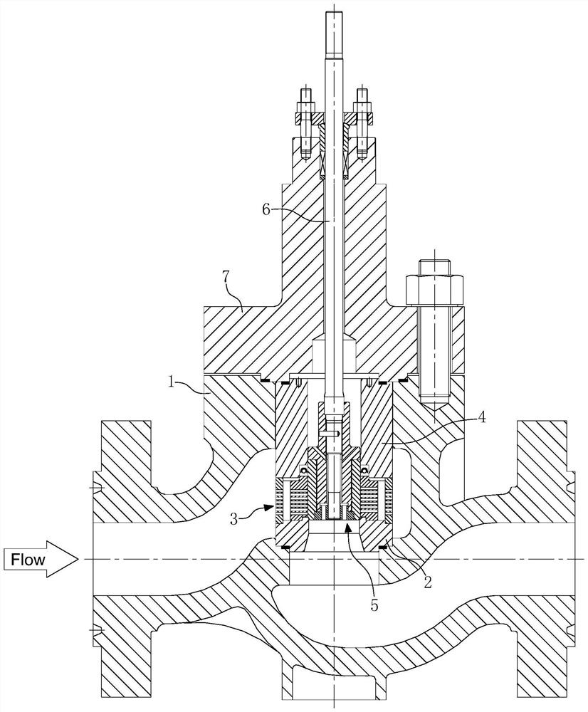
The invention discloses an erosion-resistant balanced type regulating valve which comprises a valve body, a valve seat, a sleeve, a pressing ring, a valve element and a valve rod, the valve seat, the sleeve and the pressing ring are sequentially installed in the valve body, the valve element is installed in the pressing ring and the sleeve, the valve rod is connected with the valve element, and the valve element comprises a valve element base and a valve element pressing plate which are arranged on the valve rod in a sleeving mode. The valve element pressing plate is provided with a first through hole communicated with a gap between the valve element base and the valve rod and a valve outlet, and the valve element base is provided with a second through hole communicated with the gap between the valve element base and the valve rod and the space between the valve rod and the pressing ring. According to the design, in the using process, a medium at a valve outlet can enter the gap between the valve element base and the valve rod through the first through hole in the valve element pressing plate, then overflows from the second through hole in the valve element base and fills the space between the valve rod and the pressing ring, and therefore the pressure borne by the upper portion and the lower portion of the valve element is equal; and the regulating valve is suitable for a high-pressure-difference erosion environment.

Description

technical field [0001] The invention relates to the field of valves, in particular to an erosion-resistant balance regulating valve. Background technique [0002] Erosion is one of the severe working conditions. In the case of severe erosion, the life of the control valve is extremely short, the shortest is 1-2 months, and the longest is only 3-6 months. The erosion problem is more prominent in applications such as hydrogenation catalytic devices in the petrochemical industry and copper ore slurry adjustment in mineral chemistry. [0003] Erosion mainly occurs in the case of large pressure difference and medium containing particles. In these occasions, the flow rate of the medium at the throttle port of the valve is very high, with great kinetic energy, which can quickly push the valve core and the surface of the valve seat out of the streamline-shaped groove, thereby destroying the sealing surface and causing the valve to fail. or scrapped. Especially when the valve is w...

Claims


Application Information

Patent Timeline
Patent Type & Authority Applications(China)
IPC IPC(8): F16K1/00F16K1/32F16K1/36F16K1/42F16K27/02F16K47/08
Inventor 郁学军张勇冯敏黄彬马原野雷晓霞周丽何禹珉程睿张世乐吴建
Owner WUXI SCORE AUTOMATIC CONTROL EQUIP CO LTD
Learn More