Deep hole layered slotting blasting method for rock laneway
A technology for wells and deep holes, applied in blasting, earth-moving, mining equipment, etc., can solve problems such as affecting the progress of rock roadway excavation, fixed delay time, and inability to adjust according to needs, so as to improve the utilization rate of blastholes, improve The footage and level, the effect of speeding up the construction progress
- Summary
- Abstract
- Description
- Claims
- Application Information
AI Technical Summary
Problems solved by technology
Method used
Image
Examples
Embodiment 1
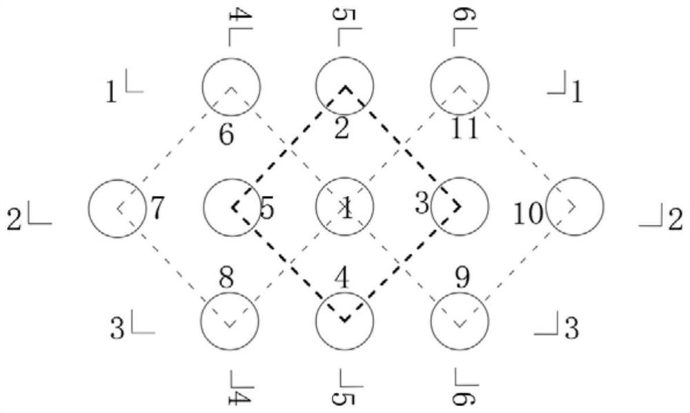
[0051] In order to solve the problem of low blasthole utilization in the deep hole cutting blasting scheme of rock roadway, see Figure 3 to Figure 6 and Figure 9 As shown, the deep hole layered cutting blasting method for rock wells and roadways provided by the embodiments of the present invention is mainly suitable for blasting operations such as rock drilling operations, tunnels, roadway operations, and mines, and is particularly suitable for roadway blasting operations; The hard rock wells mentioned above specifically refer to vertical wells with rock firmness coefficient (Platt’s coefficient) f greater than or equal to 7, and also include hard rock wells determined by any other surrounding rock classification method. The deep hole specifically refers to a blasthole with a blasthole depth greater than or equal to any depth above 3.0m, especially a blasthole with a depth of 3.0-3.4.0m in a rock roadway and a blasthole with a depth of 6.0-10.0m in a wellbore.
[0052] It i...
Embodiment 2
[0092] see Figure 5 As shown, the solution provided by the embodiment of the present invention is similar to the technical solution of the first embodiment, the difference is that the lower layers of the No. 2 and No. 4 cut holes are also charged, and the upper and lower charge parts are separated, The lower layers of the No. 2 and No. 4 cut holes adopt No. 4 detonators to detonate at last.
[0093] No. 2, No. 3, No. 4 and No. 5 cutout holes are used to detonate the upper charge parts of No. 1 electronic detonator at the same time, and the upper part of No. 1 cutout hole is used as an empty hole to improve the blasting efficiency. Then detonate the upper charge part of No. 6 to No. 11 cut holes, adopt No. 2 electronic detonator to detonate, and the time difference between the previous detonation is 10ms ~ 15ms. Finally detonate 1 to 11 times, in which No. 3 and No. 5 cut holes are in the middle of the cut area, and their lower layers are empty holes, and the lower layer of N...
Embodiment 3
[0096] see Image 6 As shown, the scheme provided by the embodiment of the present invention is basically the same as the technical scheme of Embodiments 1 and 2, the difference is that the No. 1 cutout hole is an empty hole as a whole, that is, no medicine is charged; the No. 3 and 5 The lower layer of the No. cut hole is charged, and the upper and lower charge parts are isolated.
[0097] After detonating the upper layer charges of No. 2, No. 3, No. 4 and No. 5 cutting holes in the first cutting area, the first groove cavity is formed, and the remaining detonating steps are replaced by: using No. 2 detonators to detonate No. 2, The lower charge parts of No. 3, No. 4 and No. 5 cut holes are guided by the new free surface provided by the first cavity formed after the detonation of the lower hole of No. 1 cut hole and the upper charge part of the first cut area. The lower layers of No. 2, No. 3, No. 4 and No. 5 cut holes were blasted to form the second cavity;
[0098] The No...
PUM
 Abstract
Description
Claims
Application Information
 - R&D Engineer
- R&D Manager
- IP Professional
- Industry Leading Data Capabilities
- Powerful AI technology
- Patent DNA Extraction
Browse by: Latest US Patents, China's latest patents, Technical Efficacy Thesaurus, Application Domain, Technology Topic, Popular Technical Reports.
© 2024 PatSnap. All rights reserved.Legal|Privacy policy|Modern Slavery Act Transparency Statement|Sitemap|About US| Contact US: help@patsnap.com


