Variable diameter radial uniform uncoupling continuous charging structure and charging method thereof

A technology of variable diameter and charge, which is applied in blasting and other directions, can solve the problems of reduced stability of surrounding rock, increased existence time of blasting gas, and hole wall damage, so as to overcome rock mass sandwiching effect, improve effective utilization rate, The effect of reducing the difficulty of drilling

Pending Publication Date: 2018-11-30
ANHUI UNIV OF SCI & TECH
View PDF5 Cites 8 Cited by
  • Summary
  • Abstract
  • Description
  • Claims
  • Application Information

AI Technical Summary

Problems solved by technology

For the air gap axially uncoupled charge structure, the reserved air gap can reduce the detonation pressure to a certain extent, increase the existence time of the detonation gas, and improve the quality of rock fracture and crack formation, but this charge structure is very difficult for the charge structure. The rock of the hole wall of the section will still generate a large blasting load, and the energy distribution between the charge section and the air space section in the longitudinal direction is uneven, and the energy concentration of the charge section will cause excessive damage to the surrounding rock of the hole wall at the corresponding position, resulting in The flatness of the contour surface after the explosion is poor, and the stability of some surrounding rocks is reduced
Radial air is not coupled to the charge, which can also reduce the detonation pressure and increase the life time of the detonation gas. However, since the blastholes are mostly horizontal or vertically inclined in actual operations, the explosives will cling to each other under the action of gravity. On one side of the blast hole, the energy of the explosive explosion does not act radially and evenly on the rocks around the blast hole, and local excessive damage will also occur on the side of the hole wall close to the charge, which will also lead to a rougher contour surface formed after the blast. Poor, reduced stability of some surrounding rock

Method used


Image

  • Variable diameter radial uniform uncoupling continuous charging structure and charging method thereof
  • Variable diameter radial uniform uncoupling continuous charging structure and charging method thereof
  • Variable diameter radial uniform uncoupling continuous charging structure and charging method thereof

Examples


Embodiment

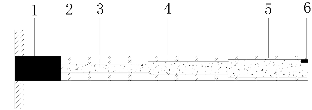
[0036] For the charging method of variable diameter radial uniform non-coupling continuous charging structure, the specific steps are as follows:

[0037] 1) Drill a peripheral hole with a diameter of D and a depth of L along the excavation contour, and determine the charge length L according to the rock and terrain conditions 1 and the plugging length L 2 ;

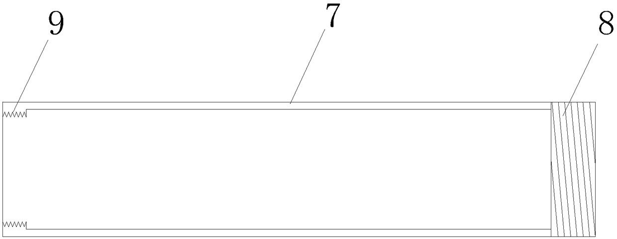
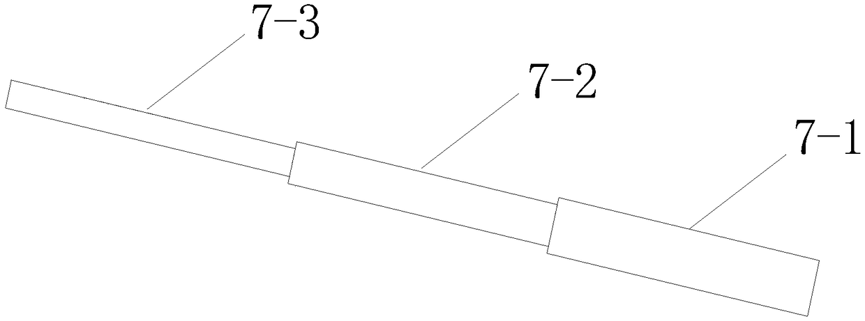
[0038] 2) According to the sequence from the bottom of the hole to the orifice, the ratio of diameter is 1.2:1:0.8, and the ratio of length is 1:1:1, select three sections of PVC pipe 7, which are No. 1 PVC pipe 7-1 and No. 2 PVC pipe The outer diameters of No. 7-2 and No. 3 PVC pipes 7-3, No. 1 PVC pipe 7-1, No. 2 PVC pipe 7-2 and No. 3 PVC pipe 7-3 are reduced in proportion to D respectively. 1 、D 2 、D 3 , the total length is equal to the design charge length L 1 ;

[0039] 3) According to the outer diameter D of No. 1 PVC pipe 7-1, No. 2 PVC pipe 7-2 and No. 3 PVC pipe 7-3 1 、D 2 、D 3 , choose the inner diame...


PUM


Abstract

The invention relates to the technical field of controlled blasting, in particular to a variable diameter radial uniform uncoupling continuous charging structure and a charging method thereof. The charging structure comprises a variable diameter charging cylinder, a positioning device, a nonel detonator and an emulsion explosive. The variable diameter charging cylinder is formed by connecting PVCpipes of different diameters, and the positioning device is fixed on the outside of the variable diameter charging cylinder. The bottom of the variable diameter charging cylinder is provided with thenonel detonator, and the variable diameter charging cylinder is filled with the emulsion explosive. A charging method of the variable diameter radial uniform uncoupling continuous charging structure is further provided. According to the structure and the method, excessive damage to the local part of the hole wall can be avoided, the surrounding rock stability and the flatness of the excavated contour surface are improved, the effective utilization rate of the explosive can be improved, the rock mass clamping effect is overcome, and the drilling difficulty of the next cycle is reduced.

Description

technical field [0001] The invention relates to the technical field of controlled blasting, in particular to a variable-diameter radial uniform non-coupling continuous charge structure and a charge method thereof. technical background [0002] During the blasting operation, due to the effect of explosive energy, it often causes different degrees of damage to the surrounding rock outside the excavation contour line, affecting the stability and integrity of adjacent structures. Peripheral hole controlled blasting is to drill dense blastholes along the excavation contour when excavating and blasting within the designed boundary range, adopt uncoupled charge structure, and detonate before or after blasting in the main blasting area, so that the blasting formed after blasting A blasting technique that has high flatness on the contour surface and can maintain the stability of the surrounding rock. [0003] At present, the peripheral hole controlled blasting technology mainly adop...

Claims


Application Information

Patent Timeline
IPC IPC(8): F42D1/08F42D3/04
CPCF42D1/08F42D3/04
Inventor 程兵汪海波吴捷豪雷小磊汪海旭杨阳王盼盼宗琦王梦想
Owner ANHUI UNIV OF SCI & TECH
Why Eureka
Try Eureka