Cutting blasting method based on kerf precutting and bottom reinforced throwing
A pre-cutting and slitting technology, applied in blasting and other directions, can solve the problems of poor cutting effect, enhanced clamping effect, poor blasting effect, etc., to improve the cutting effect, overcome the influence of surrounding rock stress, and overcome clamping effect for making
- Summary
- Abstract
- Description
- Claims
- Application Information
AI Technical Summary
Problems solved by technology
Method used
Image
Examples
Embodiment 1
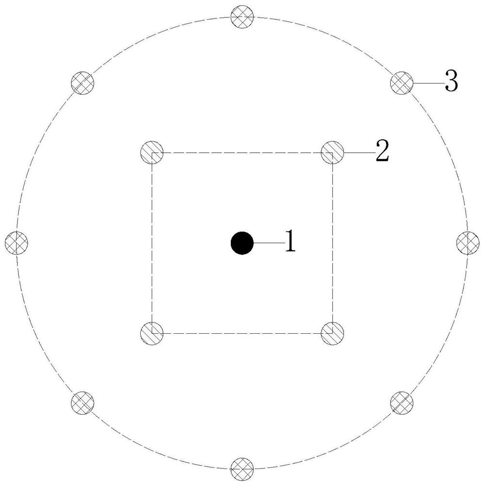
[0038] In a deep coal mine rock roadway, the cutting blasting method based on kerf pre-cutting and bottom enhanced throwing is adopted, including the following steps:
[0039] 1) Drilling: Drill a center cut hole 1 in the center of the design cut area, drill a circle of pre-cut cut holes 3 around the center cut hole 1, center cut hole 1 and pre-cut cut hole 3 Three throwing cut holes 2 are drilled between them, the center cut hole 1, the throw cut hole 2 and the pre-cut cut hole 3 have a depth of 2200mm. The depth of peripheral holes, auxiliary holes, caving holes and peripheral holes is 2000mm, and the diameter of all blast holes is 42mm;
[0040]2) Charge: 4 rolls of 35mm diameter water-gel explosives are loaded in the center slot 1, 0.8 rolls of 35mm diameter water-gel explosives are loaded at the bottom of the throwing slot 2, and the charge length of the throwing slot 2 is the center slot 1 pack 0.2 times the length of the charge, the pre-cut slotting hole 3 is filled wi...
Embodiment 2
[0044] Concrete method step is identical with embodiment 1, difference is:
[0045] The difference is that 4 throwing cut holes 2 are drilled between the center cut hole 1 and the pre-cut cut hole 3. The depth of the center cut hole 1, the throw cut hole 2 and the pre-cut cut hole 3 is 2350mm. The charge length of the throwing cut hole 2 is 0.25 times the charge length of the center cut hole 1, and the auxiliary hole, the collapse hole and the peripheral hole are drilled in sequence on the outside of the pre-cut cut hole 3, and the depth of the auxiliary hole, the collapse hole and the peripheral hole is 2000mm, the center cut hole 1 is filled with 4 volumes of water gel explosives with a diameter of 35mm, and the bottom of the throwing hole 2 is filled with a roll of water gel explosives with a diameter of 35mm. In the cutting hole 3, the charge uncoupling coefficient of the pre-cutting hole 3 is 42 / 24=1.75, and the FRP pipe with an inner diameter of 24mm and a wall thickness...
Embodiment 3
[0047] Concrete method step is identical with embodiment 1, difference is:
[0048] The difference is that 5 throwing cut holes 2 are drilled between the center cut hole 1 and the pre-cut cut hole 3. The depth of the center cut hole 1, the throw cut hole 2 and the pre-cut cut hole 3 is 2500mm. The charge length of the throwing cut hole 2 is 0.3 times the charge length of the center cut hole 1, and the auxiliary hole, the collapse hole and the peripheral hole are drilled in sequence on the outside of the pre-cut cut hole 3, and the depth of the auxiliary hole, the collapse hole and the peripheral hole is 2000mm, the center cut hole 1 is loaded with 4 volumes of water gel explosives with a diameter of 35mm, and the bottom of the throwing hole 2 is filled with 1.2 rolls of water gel explosives with a diameter of 35mm. In the cutting hole 3, the non-coupling coefficient of the pre-cutting hole 3 is 42 / 21=2.0, and the FRP pipe with an inner diameter of 21mm and a wall thickness of ...
PUM
 Abstract
Description
Claims
Application Information
 - R&D
- Intellectual Property
- Life Sciences
- Materials
- Tech Scout
- Unparalleled Data Quality
- Higher Quality Content
- 60% Fewer Hallucinations
Browse by: Latest US Patents, China's latest patents, Technical Efficacy Thesaurus, Application Domain, Technology Topic, Popular Technical Reports.
© 2025 PatSnap. All rights reserved.Legal|Privacy policy|Modern Slavery Act Transparency Statement|Sitemap|About US| Contact US: help@patsnap.com


