Uncoupled continuous charge structure with eccentric retaining wall and its application method

A charging and eccentric technology, used in manufacturing tools, ceramic molding machines, blasting, etc., can solve problems such as increased blasting cost, detonating cord damage, excessive damage, etc., to improve energy utilization, save economic costs, overcome clamping effect for making

Active Publication Date: 2021-09-07
安徽江南爆破工程有限公司
View PDF0 Cites 0 Cited by
  • Summary
  • Abstract
  • Description
  • Claims
  • Application Information

AI Technical Summary

Problems solved by technology

However, since the blast holes are mostly inclined horizontally or vertically in actual operations, the explosives will cling to one side of the blast holes under the action of gravity, forming an eccentric uncoupled charge. At this time, the energy of the explosive explosion does not act radially and uniformly. For the rock around the blast hole, the rock mass near the side of the charge roll will be excessively damaged. Since the position of the charge roll is uncontrollable, when the charge roll is close to the wall of the side hole that needs to be protected, it will cause excessive damage to the rock mass on the side that needs to be protected, resulting in a blast. The flatness of the formed contour surface is poor, and the stability of some surrounding rocks is reduced
[0004] In the process of smooth surface blasting, the detonating cord and No. 2 rock explosives are usually used to bind the explosives in series on the bamboo chips. The operation is complicated and the work efficiency is low. The problem of leakage of explosives leads to the failure of blasting to produce blind blasting, which brings serious safety hazards to blasting construction, and the unit price of detonating cord is high, and a large number of uses will increase the cost of blasting

Method used


Image

  • Uncoupled continuous charge structure with eccentric retaining wall and its application method
  • Uncoupled continuous charge structure with eccentric retaining wall and its application method
  • Uncoupled continuous charge structure with eccentric retaining wall and its application method

Examples


Embodiment 1

[0033] Example 1: In controlled blasting of peripheral holes,

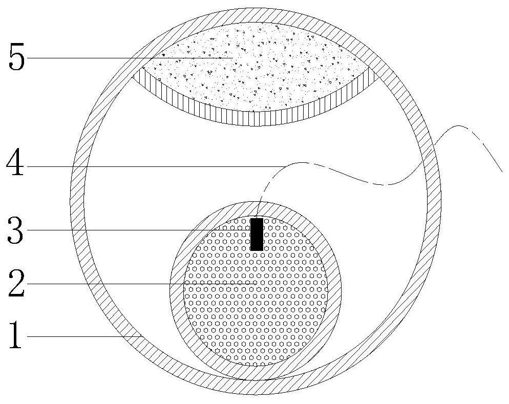
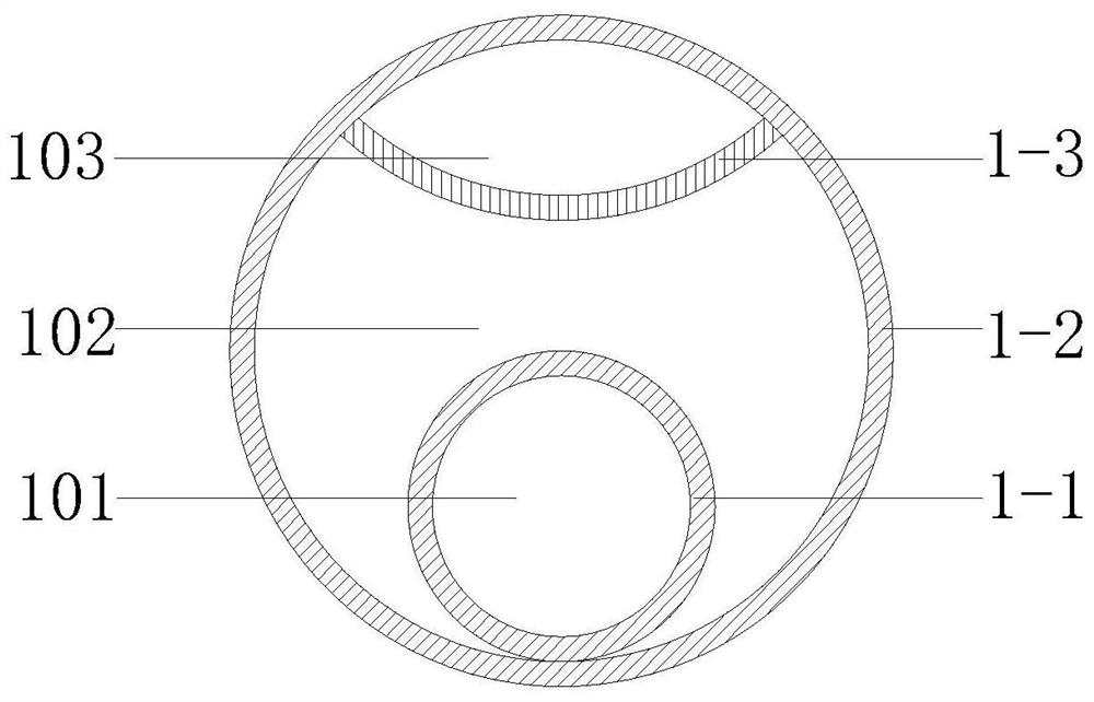
[0034] refer to Figure 1-4 , an eccentric retaining wall uncoupled continuous charging structure, comprising a PVC pipe 1, explosives 2, nonel detonator 3 and high wave impedance material 5, the PVC pipe 1 includes a charging pipe 1-1, a positioning pipe 1-2 and Arc partition 1-3, the charging tube 1-1 is located at the lower part of the inner cavity of the positioning tube 1-2, the upper part of the inner cavity of the positioning tube 1-2 is provided with an arc-shaped partition 1-3, and the charging tube 1-2 1 and arc-shaped partitions 1-3 are arranged along the axial direction of the PVC pipe 1 and the length is compatible with the PVC pipe 1. The internal space of the positioning pipe 1-2 is divided into a charge chamber 101, an air chamber 102 and a wall chamber from bottom to top. 103, the charge cavity 101 is filled with explosives 2, the explosives 2 are preferably No. 2 rock explosives, the bottom of t...

Embodiment 2

[0049] The non-coupling continuous charge structure of the eccentric retaining wall is the same as that of embodiment 1, and the different method steps are as follows:

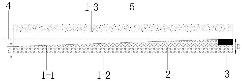
[0050] The diameter of the charge tube increases from the orifice end to the bottom of the hole, and the diameter D at the bottom of the charge tube hole is proportional to the diameter d at the orifice end of the charge tube, D: d=1.3.

[0051] The explosive is emulsion explosive.

[0052] The components of high wave impedance concrete stones are Portland cement, iron sand, water and admixture, the Portland cement and the iron sand are mixed uniformly at a mass ratio of 1:5.0, and the water-cement mass ratio is 0.5, so The mass of the above-mentioned admixture is 4% of the mass of Portland cement. The admixture is composed of an accelerator and a hardening accelerator at a mass ratio of 1:1.5, and the mixture is evenly mixed to obtain high-wave impedance concrete, and then the high-wave impedance concrete is ...

Embodiment 3

[0054] The diameter of the charge tube increases from the orifice end to the bottom of the hole, and the diameter D at the bottom of the charge tube hole is proportional to the diameter d at the orifice end of the charge tube, D: d=1.2.

[0055] The explosive is a powdered explosive.

[0056] The components of the high wave impedance concrete stones are Portland cement, iron sand, water and admixtures, the Portland cement and the iron sand are uniformly mixed at a mass ratio of 1:3.0, and the water-cement mass ratio is 0.4 , the mass of the admixture is 4% of the mass of Portland cement, the admixture is formed by mixing the accelerator and the hardening agent at a mass ratio of 1:1.3, and the mixture is evenly mixed to obtain high-wave impedance concrete, and then the high-wave impedance concrete Pour it into the mold and take it out after 7 days of curing.


PUM

PropertyMeasurementUnit
densityaaaaaaaaaa
densityaaaaaaaaaa

Abstract

The present invention relates to an eccentric retaining wall uncoupled continuous charging structure, including PVC pipe, explosive, nonel detonator and high wave impedance material, characterized in that: the PVC pipe includes charging pipe, positioning pipe and arc-shaped partition, The charging tube is located at the lower part of the inner cavity of the positioning tube, and an arc-shaped partition is arranged on the upper part of the inner cavity of the positioning tube. The inner space of the positioning tube is divided into a charging cavity, an air cavity and a wall cavity from bottom to top. Explosives are loaded, a detonator detonator is placed at the bottom of the charge tube hole, and the detonator of the detonator detonator is drawn out from the air cavity, and high wave impedance materials are filled in the retaining wall cavity. The invention also provides the corresponding usage method of the charge structure. The invention can fully destroy the rock mass on the blasted side, reduce the damage to the rock mass on the side to be protected, ensure the stability of the surrounding rock and the flatness of the excavation profile surface, overcome the sandwiching effect of the rock mass, improve the energy utilization rate of the explosive, and is easy to operate. High work efficiency, good safety, saving economy.

Description

technical field [0001] The invention relates to the technical field of controlled blasting, in particular to an eccentric retaining wall uncoupled continuous charge structure and a use method thereof. Background technique [0002] During the blasting operation, due to the effect of explosive energy, it often causes different degrees of damage to the surrounding rock outside the excavation contour line, affecting the stability and integrity of adjacent structures. Peripheral hole controlled blasting is to drill dense blastholes along the excavation contour when excavating and blasting within the designed boundary range, adopt uncoupled charge structure, and detonate before or after blasting in the main blasting area, so that the blasting formed after blasting A blasting technique that has high flatness on the contour surface and can maintain the stability of the surrounding rock. [0003] At present, the peripheral hole control blasting technology often adopts the radial air...

Claims


Application Information

Patent Timeline
Patent Type & Authority Patents(China)
IPC IPC(8): F42D1/00F42D3/04B28B7/00C04B28/04
Inventor 高朋飞马国强郑永东杨翎马立飞金鹏刘阳春
Owner 安徽江南爆破工程有限公司
Why Eureka
Try Eureka