Device capable of continuously using fluorescent film sensor and application thereof

A thin-film sensor and fluorescent technology, applied in the field of fluorescent sensors, can solve the problems of decreased sensitivity, decreased sensitivity, and reduced sensitivity, and achieve the effects of avoiding lifespan decline, improving detection lifespan, and solving cross-contamination

Pending Publication Date: 2022-04-01
BEIJING HUATAI NOVA TECH
View PDF0 Cites 0 Cited by
  • Summary
  • Abstract
  • Description
  • Claims
  • Application Information

AI Technical Summary

Problems solved by technology

[0004] However, the fluorescence intensity and sensitivity of fluorescent sensitive materials decay rapidly with the use time. There are many reasons for this, and it is difficult to avoid in actual use.
First of all, some fluorescent materials change the spectrum through chemical reactions, so the sensitivity of materials that have been used for a period of time will gradually decrease until they fail completely, so they need to be replaced
Second, because the fluorescence sensor needs to use excitation light to make the material enter the excited state during use, and the electrons of the excited state molecules are at a high energy level, which is easy to interact with water, oxygen and other substances in the fluid and deteriorate, resulting in a decrease in sensitivity
Third, with multiple detection processes, solid dust particles from the air or liquid will often be irreversibly adsorbed with the contact between the fluid and the surface of the sensing material, reducing the sensitivity
Therefore, although the lifespan of the material can be improved from the aspects of material design, selection of excitation light, and optimization of the working mode of the fluorescence detection equipment, the need for frequent replacement of sensor elements still exists, and artificial replacement brings inconvenience to the field that requires long-term detection.
However, using a mechanical structure to simulate human actions to replace fluorescent sensitive materials or their carriers requires more complex equipment and larger equipment volume.

Method used


Image

  • Device capable of continuously using fluorescent film sensor and application thereof
  • Device capable of continuously using fluorescent film sensor and application thereof

Examples


Embodiment

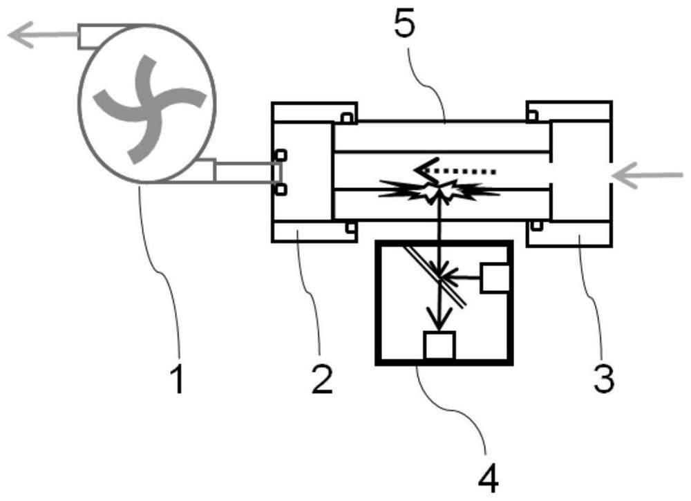
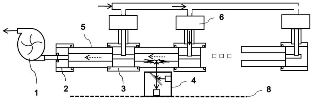
[0031] Such as figure 2 As shown, the present invention provides a device that can continuously use fluorescent thin film sensors, and adopts the method of connecting multiple fluorescent thin film capillaries 5 in series to achieve the purpose of greatly reducing the replacement frequency of sensitive components. The detection path consists of a fluid pump 1, a thin fluorescent thin tube 5, a communication device 3 for a three-way fluid passage, a solenoid valve 6 and a universal inlet. When the sensitivity of a fluorescent thin tube 5 close to the fluid pump 1 decreases and needs to be abandoned, the fluorescent detection unit 4 moves to the next fluorescent thin tube 5 on the electronically controlled slide rail 8, corresponding to the position of the fluorescent thin tube 5. The solenoid valve 6 is opened, and the rest of the solenoid valves 6 are closed, so that the fluid only enters the new thin tube of fluorescent film 5 through the solenoid valve 6 . In addition, the...


PUM


Abstract

The invention relates to a device capable of continuously using a fluorescent thin film sensor, which comprises a fluid pump, a fluorescence detection unit, a fluid inlet, a fluid outlet, an electric control slide rail, a plurality of communication devices and a plurality of fluorescent thin film slim tubes, and the plurality of fluorescent thin film slim tubes are alternately communicated with the plurality of communication devices to realize sequential series connection. The fluid pump is arranged at the fluid outlet and provides negative pressure, the electric control sliding rail is laid in the arrangement direction of the fluorescent thin film tubules, the fluorescence detection unit is installed on the electric control sliding rail and can reciprocate along the electric control sliding rail, a light-emitting module of the fluorescence detection unit faces the fluorescent thin film tubules, and the fluorescent thin film tubules are arranged on the fluorescent detection unit. The fluid inlet can be used for introducing fluid to be detected into any fluorescent thin film thin tube through the communicating device. In addition, the invention also discloses a method for detecting the fluorescent film by using the device. Therefore, the replacement frequency of the solid fluorescent sensitive material can be greatly reduced.

Description

technical field [0001] The invention belongs to the technical field of fluorescent sensors, and in particular relates to a device capable of continuously using a fluorescent thin film sensor and its application. Background technique [0002] Fluorescent sensors have the advantages of high sensitivity, high selectivity, small size, and low cost. In recent years, they have become a widely used sensor design principle. The core principle is to design fluorescent materials with specific selectivity. When these materials Specific fluorescence spectral changes can be produced after contact with target substances. Therefore, whether there is a target detection substance can be determined by monitoring the spectral change of the fluorescent material. When the substance to be detected is a fluid, in order to improve the response speed and detection efficiency, solid fluorescent materials are often used to detect it. In order to further improve the sensitivity, the detection materia...

Claims


Application Information

Patent Timeline
Patent Type & Authority Applications(China)
IPC IPC(8): G01N21/64
Inventor 王辰粟勇韩俊袁丁吴红彦夏征
Owner BEIJING HUATAI NOVA TECH
Why Eureka
Try Eureka