Mechanical clamp for clamping optical lens

An optical lens and mechanical technology, applied in the field of optical applications, can solve the problems of low stability and high cost, and achieve the effect of high stability, low cost and uniform strength

Pending Publication Date: 2022-04-01
中国电子科技集团公司第五十三研究所
View PDF7 Cites 0 Cited by
  • Summary
  • Abstract
  • Description
  • Claims
  • Application Information

AI Technical Summary

Problems solved by technology

Through the analysis, it can be seen that the cost of mechanical fixtures is low, but the stability is low; the cost of pneumatic fixtures and vacuum adsorption fixtures is relatively high

Method used


Image

  • Mechanical clamp for clamping optical lens

Examples


Embodiment Construction

[0027] In order to enable those skilled in the art to better understand the solutions of the present application, the technical solutions of the embodiments of the present application will be clearly and completely described below in conjunction with the drawings in the embodiments of the present application.

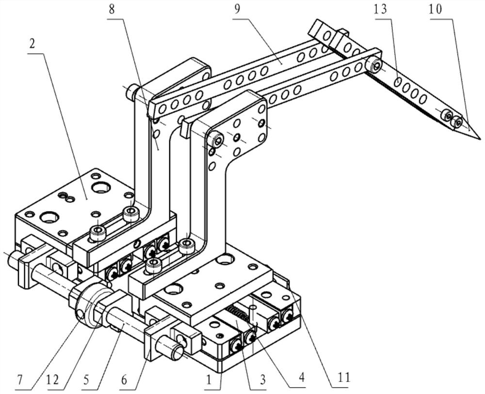
[0028] A mechanical fixture for clamping optical lenses, including a base 1, two moving components, two clamping components, a lead screw component and a clamping head 10; after the two moving components are respectively installed with a clamping component, the whole Installed on the base 1, at the same time, the two moving components are driven by the screw component to perform reverse synchronous movement on the base 1, thereby adjusting the distance between the two clamping components, so that it is installed between the two clamping components The clamping head 10 between clamps or releases the optical lens.

[0029] Optionally, the clamping head 10 is made of plast...


PUM


Abstract

The invention provides a mechanical clamp for clamping an optical lens. The mechanical clamp comprises a base, two moving assemblies, two clamping assemblies, a lead screw assembly and a clamping head. The two clamping assemblies are driven by the lead screw assembly to move synchronously in the reverse direction to adjust the clamping heads with high precision, the clamping precision of the whole clamp can be guaranteed, the stress unevenness of the two sides of the optical lens in the clamping process can be eliminated, stable clamping and installation of the optical lens are achieved, and the clamping device has the advantages of being low in cost and high in stability.

Description

technical field [0001] The invention belongs to the field of optical applications, in particular to a mechanical clamp for clamping optical lenses. Background technique [0002] Semiconductor lasers, which use semiconductor materials as working substances, have broad application prospects in optical communications, optical storage, and laser processing due to their small size, light weight, and ease of use. Therefore, since the semiconductor laser uses an asymmetric active channel, the laser beam emitted by the end face has a large divergence angle, which can be as high as θ=20° and θ=60° in the parallel and vertical directions. Therefore, the beam collimation of the semiconductor laser becomes an indispensable step. [0003] At present, in the beam collimation process of semiconductor lasers, since the semiconductor chip and the corresponding collimating lens are relatively small in size, slight installation errors will cause beam collimation failure, and the installation ...

Claims


Application Information

Patent Timeline
Patent Type & Authority Applications(China)
IPC IPC(8): G02B27/62G02B7/02H01S5/00
Inventor 安朝卫王毕艺刘彤宇李宇海张悦玲
Owner 中国电子科技集团公司第五十三研究所
Why Eureka
Try Eureka