Clamping and sealing method for ultrahigh-vacuum-degree exhaust equipment of hemispherical resonator gyroscope

A hemispherical resonant gyro, ultra-high vacuum technology, applied in shearing machine equipment, metal processing equipment, pipe shearing devices, etc., can solve problems such as high pressure, reduce production efficiency, affect device production work, etc., achieve consistent position, and improve work. The effect of efficiency

Pending Publication Date: 2022-04-05
CHINA ELECTRONICS TECH GRP NO 26 RES INST
View PDF0 Cites 0 Cited by
  • Summary
  • Abstract
  • Description
  • Claims
  • Application Information

AI Technical Summary

Problems solved by technology

The current equipment has the following problems. During the production process of the oxygen-free copper tube, a part of the gas is more or less mixed. When the encapsulation is performed, if the encapsulation speed is too fast, the gas released by the deformation of the oxygen-free copper tube If it is too late to remove it, it will penetrate into the device and destroy the existing vacuum.
At present, the equipment uses an electric oil pump combined with manual clamps for clamping and sealing. The pressure provided by the electric oil pump is high, and the staff's clamping time is extremely short. According to the comparison test of slow speed clamping, the oxygen-free copper tube is in the clamping seal. During the process, the extrusion deformation of the copper tube did release gas, and caused the vacuum degree to drop by two orders of magnitude
If the clamping speed is too fast, it is too late to pump out the gas, which will reduce the vacuum and affect the subsequent production of the device
In addition, manual clamping is used for clamping and sealing, and there will be inconsistencies in the position of clamping and sealing, which also greatly reduces production efficiency.

Method used


Image

  • Clamping and sealing method for ultrahigh-vacuum-degree exhaust equipment of hemispherical resonator gyroscope
  • Clamping and sealing method for ultrahigh-vacuum-degree exhaust equipment of hemispherical resonator gyroscope
  • Clamping and sealing method for ultrahigh-vacuum-degree exhaust equipment of hemispherical resonator gyroscope

Examples


Embodiment Construction

[0023] The present invention will be described in further detail below in conjunction with the accompanying drawings and specific embodiments.

[0024] The hemispherical resonant gyro ultra-high vacuum exhaust equipment clamping method of the present invention, the steps are as follows,

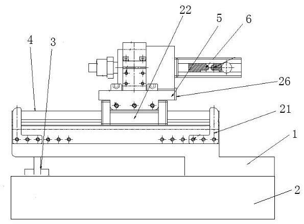
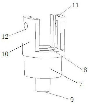
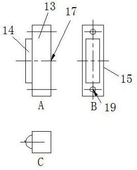
[0025] 1) First obtain the clamping device for the ultra-high vacuum exhaust equipment of the hemispherical resonator gyroscope;

[0026] 2) Then the exhaust pipe of the hemispherical resonant gyro ultra-high vacuum exhaust equipment is clamped for the first time by the clamping device. At the same time of clamping, the vacuum equipment is used to suck the gas released when the exhaust pipe is deformed ;When clamping for the first time, do not pinch off the exhaust pipe;

[0027] 3) When the vacuum degree display of the vacuum equipment returns to the normal display, then follow step 2) to perform the next clamping of the exhaust pipe on the basis of the previous clamping;

[0028] 4) Repea...


PUM


Abstract

The invention discloses a clamping and sealing method for ultrahigh-vacuum-degree exhaust equipment of a hemispherical resonator gyroscope. The clamping and sealing method comprises the following steps: 1) firstly, obtaining a clamping and sealing device for the ultrahigh-vacuum-degree exhaust equipment of the hemispherical resonator gyroscope; (2) clamping the exhaust pipe of the ultrahigh vacuum degree exhaust equipment of the hemispherical resonator gyroscope for the first time by using a clamping and sealing device, and starting vacuumizing equipment to suck gas released when the exhaust pipe deforms while clamping; when the exhaust pipe is clamped for the first time, the exhaust pipe is not pinched off; (3) when the vacuum degree reading of the vacuumizing equipment is recovered to the normal reading, the exhaust pipe is clamped next time on the basis of the previous clamping according to the step (2); 4, the step 3 is repeated according to the preset clamping times until the exhaust pipe is sealed off The low-speed clamping and sealing of the exhaust copper pipe can be achieved, it can be ensured that gas released by deformation of the copper pipe is completely absorbed, and the original vacuum degree of a device is not affected.

Description

technical field [0001] The invention relates to a hemispherical resonant gyro ultra-high vacuum exhaust equipment clamping method, which is used for the hemispherical resonant gyroscope after vacuum exhausting and belongs to the technical field of hemispherical resonant gyroscope exhaust pipe clamping. Background technique [0002] Sealing refers to the process of sealing off the exhaust pipe after the exhaust of the vacuum device is completed, so as to separate the device from the exhaust system. For the sealing of vacuum devices, the exhaust pipe is made of glass, and the method of fusing (burning) is generally adopted; sealed). Clamping is to use special sealing clamps (usually manual steel shears, or gear transmission or hydraulic transmission) to squeeze and shear the oxygen-free copper exhaust pipe. The current equipment has the following problems. During the production process of the oxygen-free copper tube, a part of the gas is more or less mixed. When the encapsul...

Claims


Application Information

Patent Timeline
IPC IPC(8): B23D21/00B23D33/02
Inventor 甘海波朱彤杨澜方仲祺彭凯雷霆杨德胜蒋长虹许云华卜继军张挺杨勇
Owner CHINA ELECTRONICS TECH GRP NO 26 RES INST
Why Eureka
Try Eureka