Supercharge Your Innovation With Domain-Expert AI Agents!

Hydrolysis acidification reaction tank for waste treatment

A technology of hydrolytic acidification and reaction tank, which is applied in the direction of anaerobic digestion treatment, etc., can solve the problem that the water inlet cannot be effectively operated, and achieve the effects of easy agitation and sludge discharge, fast drainage speed, and avoiding blockage

Active Publication Date: 2022-04-05
ANHUI ANTAI AGRI DEV
View PDF16 Cites 0 Cited by
  • Summary
  • Abstract
  • Description
  • Claims
  • Application Information

AI Technical Summary

Problems solved by technology

The device in the above-mentioned patent has the following disadvantages: since the water inlet is located below the screen, when the height of the silt exceeds the height of the water inlet, it will cause the water inlet to be unable to perform water inlet operation effectively. Therefore, it is urgent to design a device for Hydrolysis and acidification reaction tank for waste sewage treatment to solve the above problems

Method used


Image

  • Hydrolysis acidification reaction tank for waste treatment
  • Hydrolysis acidification reaction tank for waste treatment
  • Hydrolysis acidification reaction tank for waste treatment

Examples


Embodiment 1

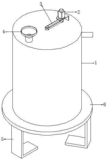
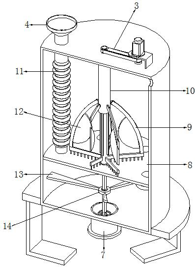
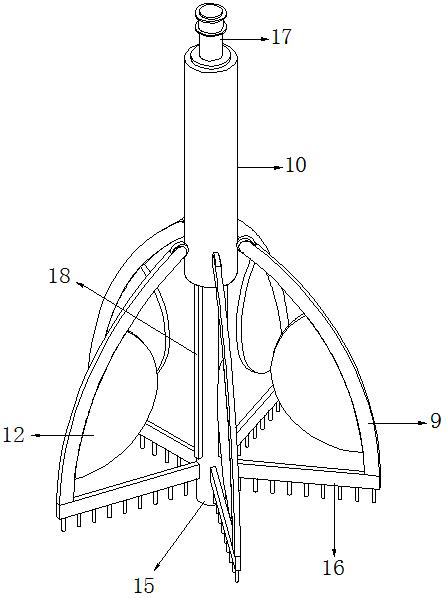
[0031] refer to Figure 1-6 , a hydrolysis and acidification reaction tank for waste sewage treatment, including a tank body 1, the middle position of the top of the tank body 1 is connected with a drum 10 through a bearing, and the top of the drum 10 is provided with a driving mechanism, and the inner wall of the drum 10 A fixed rod 15 is plugged in, and a limit structure is arranged between the outer wall of the fixed rod 15 and the inner wall of the drum 10. The bottom of the outer wall of the fixed rod 15 is connected with a water seepage net 8 through a bearing, and the peripheral outer wall of the water seepage net 8 is connected to the pool body 1 The outer wall of the fixed rod 15 close to the top of the seepage net 8 is provided with a mixed structure, and the top of the seepage net 8 is provided with equidistant circular holes distributed in a ring, and the inner wall of one of the circular holes is welded with a liquid guide Pipe 20, the top side of the tank body 1 ...

Embodiment 2

[0040] refer to Figure 7 , a hydrolysis acidification reaction tank for waste sewage treatment. Compared with Example 1, the corner of the bottom inner wall of the pool body 1 is connected with an annular material guide seat 25 by bolts, and the inner wall of the annular material guide seat 25 Set to bevel structure.

[0041] Working principle: When in use, the user quickly discharges the silt and other impurities at the bottom of the pool body 1 through the annular material guide seat 25, so as to avoid sludge and other impurities remaining at the bottom corner of the pool body 1.


PUM


Abstract

The invention discloses a hydrolytic acidification reaction tank for waste treatment, which comprises a tank body, the middle position of the top of the tank body is connected with a rotary drum through a bearing, the top of the rotary drum is provided with a driving mechanism, the inner wall of the rotary drum is inserted with a fixed rod, and a limiting structure is arranged between the outer wall of the fixed rod and the inner wall of the rotary drum. A water seepage net is connected to the bottom of the outer wall of the fixing rod through a bearing, the circumferential outer wall of the water seepage net is matched with the circumferential inner wall of the tank body, and a mixing structure is arranged on the outer wall, close to the top of the water seepage net, of the fixing rod. The problem that water cannot be effectively fed into the liquid guide pipe due to the fact that the height of impurities such as sludge and dirt in the tank body exceeds the bottom of the liquid guide pipe is solved, the top of the tank body can be stirred by utilizing an arc-shaped frame and a stirring blade, and the top of a water seepage net is brushed by utilizing a brushing plate; the drainage speed of the whole tank body is higher, and the problem of blockage of the sludge discharge pipe is avoided.

Description

technical field [0001] The invention relates to the technical field of waste sewage treatment, in particular to a hydrolysis acidification reaction tank for waste sewage treatment. Background technique [0002] Hydrolysis refers to the biochemical reaction outside the cell before the organic matter enters the microbial cell. Acidification is a typical fermentation process, and the metabolites of microorganisms are mainly various organic acids. Mechanistically speaking, hydrolysis and acidification are two stages of anaerobic nitrification process, but different processes have different treatment purposes of hydrolysis and acidification. The purpose of hydrolysis in the hydrolytic acidification-aerobic biological treatment process is mainly to convert the non-dissolved organic matter in the original wastewater into dissolved organic matter, especially in industrial wastewater, mainly to convert the difficult-to-biodegradable organic matter into easily biodegradable organic m...

Claims


Application Information

Patent Timeline
Patent Type & Authority Applications(China)
IPC IPC(8): C02F3/28
CPCY02W10/10
Inventor 杨勇
Owner ANHUI ANTAI AGRI DEV
Features
  • R&D
  • Intellectual Property
  • Life Sciences
  • Materials
  • Tech Scout
  • Unparalleled Data Quality
  • Higher Quality Content
  • 60% Fewer Hallucinations
Learn More