Crank mechanism with pistons connected in series and double connecting rods

A crank mechanism and double connecting rod technology, applied in mechanical equipment, machines/engines, etc., can solve problems such as exhaust advance angle, vulnerable connecting parts, engine vibration, etc., to achieve high power use efficiency and stable operation of the mechanism , The effect of improving engine life

Inactive Publication Date: 2022-04-05
孙鑫
View PDF2 Cites 1 Cited by
  • Summary
  • Abstract
  • Description
  • Claims
  • Application Information

AI Technical Summary

Problems solved by technology

The 4-cylinder engine does not consider the exhaust advance angle, and can work continuously. The output of the three-cylinder engine is very inconsistent. The crankshaft angle of each cylinder of the three-cylinder engine is only 180 degrees, so there is a 60-degree pause area, causing the engine Vibration is hard to avoid
The motion trajectory of the outer edge of the crankshaft is not a circular trajectory. The fixed end of the deflection shaft is used as the power output shaft instead of the crankshaft. The deflection shaft and the crankshaft have relative motion, and the multi-cylinder power output is likely to cause the connecting parts to be vulnerable.

Method used


Image

  • Crank mechanism with pistons connected in series and double connecting rods
  • Crank mechanism with pistons connected in series and double connecting rods
  • Crank mechanism with pistons connected in series and double connecting rods

Examples


Embodiment 1

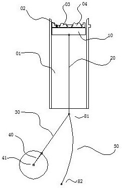
[0034] Embodiment one, combining figure 1 , 2 , 3, a kind of engine structure, comprises cylinder block 01, spark plug and fuel injection assembly 02, intake valve 03, exhaust valve 04, piston 10, and piston 10 is hinged upper connecting rod 20, and one end of upper connecting rod 20 is hinged simultaneously The lower connecting rod 30 and the sliding block on the arc guide rail 50 ; the lower connecting rod 30 is hinged to the crankshaft 40 , and the crankshaft 40 pushes the crankshaft 41 . The structural parameters of this engine are: if the stroke of the piston 10 is set to 100, the length of the upper connecting rod 20 is 110, the length of the lower connecting rod 30 is 67.8, the length of the crankshaft 40 is 20, and the arc guide rail is 50. The radius of curvature is 128.44.

[0035] Since the present invention uses the lower connecting rod 30 and the arc-shaped guide rail 50, the stressed position of the crankshaft 40 is changed, and the rotation angle of the piston...

Embodiment 2

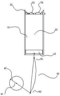
[0036] Embodiment two, combining Figure 4 , an engine structure, the difference from Embodiment 1 is that the curved guide rail 50 is hinged to the frame at the lower end point 82 of the upper link, and a motor-driven motor is provided below the upper end point 81 of the upper link. The cam 61 is provided with a hinged shift fork 62 in the groove of the cam 61 , and the shift fork 62 is slidably connected with the arc guide rail 50 .

[0037] The motor drives the cam 61 to rotate, and the cam 61 drives the shift fork 62 to shift, and the shift of the shift fork 62 causes the arc-shaped guide rail 50 to swing along the lower end point 82 of the upper connecting rod, thereby resulting in a change in the stroke of the piston 10, resulting in a change in the compression ratio. It is beneficial for the engine to be suitable for various power outputs. Other structures and principles are the same as those in Embodiment 1, and will not be repeated here.

Embodiment 3

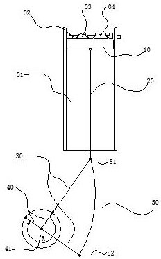
[0038] Embodiment three, combining Figure 5 , an engine structure, the difference from Embodiment 1 is that: the curved surface guide rail 50 is hinged to the frame at the lower end point 82 of the upper link, and a motor-driven wire is provided below the upper end point 81 of the upper link. The rod 63 and the lead screw 63 drive the nut 64, the nut 64 is hinged with a shift fork 62, and the shift fork 62 is slidably connected with the arc surface guide rail 50.

[0039] The motor drives the lead screw 63 to rotate, and the lead screw 63 drives the nut 64 hinged with the shift fork 62 to shift. The shift of the shift fork 62 causes the curved guide rail 50 to swing along the lower end point 82 of the upper link, thereby resulting in a change in the stroke of the piston 10. It leads to a change in the compression ratio, which is beneficial for the engine to be suitable for various power outputs. Other structures and principles are the same as those in Embodiment 1, and will ...


PUM


Abstract

The invention relates to the technical field of power machines, in particular to a piston series-connection double-connecting-rod crank mechanism which comprises a cylinder body, a piston, a crankshaft and a rack and is characterized in that double connecting rods connected in series are hinged between the piston and the crankshaft, the hinged ends of an upper connecting rod and a lower connecting rod are hinged to a sliding block or a swing arm at the same time, and the sliding block is in sliding connection with a guide rail; the swing arm is hinged with the rack; the other end of the lower connecting rod is hinged with the crankshaft handle; the stroke of the piston is more than two times larger than the length of the crankshaft handle, and the difference between the ascending running speed and the descending running speed of the piston is 1.4-3 times. By means of the double connecting rods connected in series, lateral force borne by the piston is reduced, the service life of an engine is prolonged, meanwhile, the up-down operation speed and time of the piston are different, the acting angle of the crankshaft reaches 210-270 degrees, the power use efficiency is higher, and mechanism operation is more stable.

Description

technical field [0001] The invention relates to the technical field of a power machine, in particular to a piston series double-link crank mechanism. Background technique [0002] The piston crank structure is widely used in engines and other machinery. A 4-stroke engine, without considering the exhaust advance angle, usually completes a work cycle when the crankshaft rotates 720 degrees, and the intake piston goes from top dead center to bottom dead center. Crankshaft rotation angle of 180°, compression stroke, piston bottom dead center to top dead center, crankshaft rotation angle of 180°, power stroke, piston top dead center to bottom dead center, crankshaft rotation angle of 180°, exhaust stroke, piston bottom dead center to top dead center The point crank angle is 180 degrees, and the crank angle of each stroke is 180 degrees. The 4-cylinder engine does not consider the exhaust advance angle, and can work continuously. The output of the three-cylinder engine is very in...

Claims


Application Information

Patent Timeline
Patent Type & Authority Applications(China)
IPC IPC(8): F02B75/32F02B75/04
CPCF02B75/32F02B75/045
Inventor 孙鑫
Owner 孙鑫
Why Eureka
Try Eureka