

Double-oil-way nozzle structure and nozzle system thereof
A dual oil circuit and nozzle technology, applied in the direction of charging system, fuel injection device, machine/engine, etc., can solve the problems of low atomization quality and low quality of fuel and air mixing, and achieve good results
- Summary
- Abstract
- Description
- Claims
- Application Information
AI Technical Summary
Problems solved by technology
Method used
Image

Examples
Embodiment 1
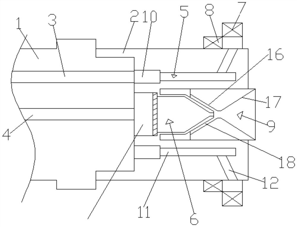
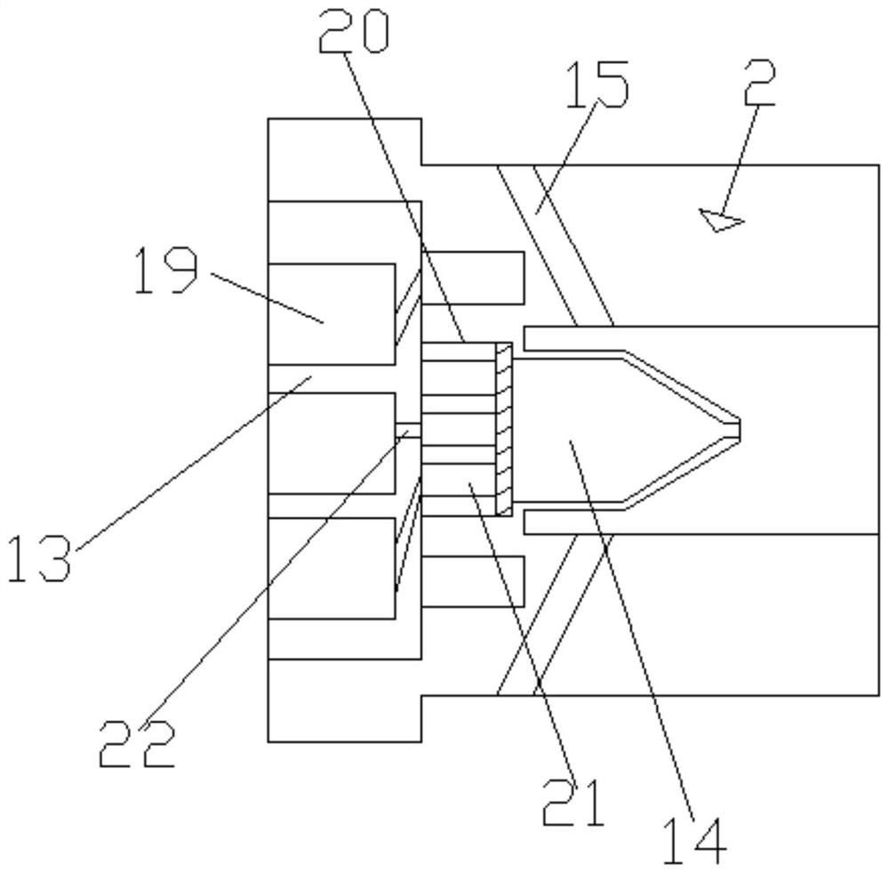
[0032] see Figure 1-7 , according to an embodiment of the present invention, a dual-oil nozzle structure includes an oil supply pipe seat 1 and a nozzle seat 2, the oil supply pipe seat 1 is provided with a main oil pipe 3 and an auxiliary oil pipe 4, and the inside of the nozzle seat 2 A main oil passage mechanism 5 connected to the main oil pipe 3 is arranged, and an auxiliary oil passage mechanism 6 connected to the auxiliary oil pipe 4 is arranged inside the nozzle seat 2. The output end of the main oil passage mechanism 5 A radial swirler 7 and an axial swirler 8 are provided, a Rafal nozzle 9 is provided on the output end of the auxiliary oil passage mechanism 6, and the main oil passage mechanism 5 includes a An annular groove 10 near one end of the oil supply pipe seat 1 and arranged along the circumference of the nozzle seat 2, the annular groove 10 communicates with the main oil pipe 3 correspondingly, and the main oil pipe 10 is connected to the annular groove 10 ...
Embodiment 2
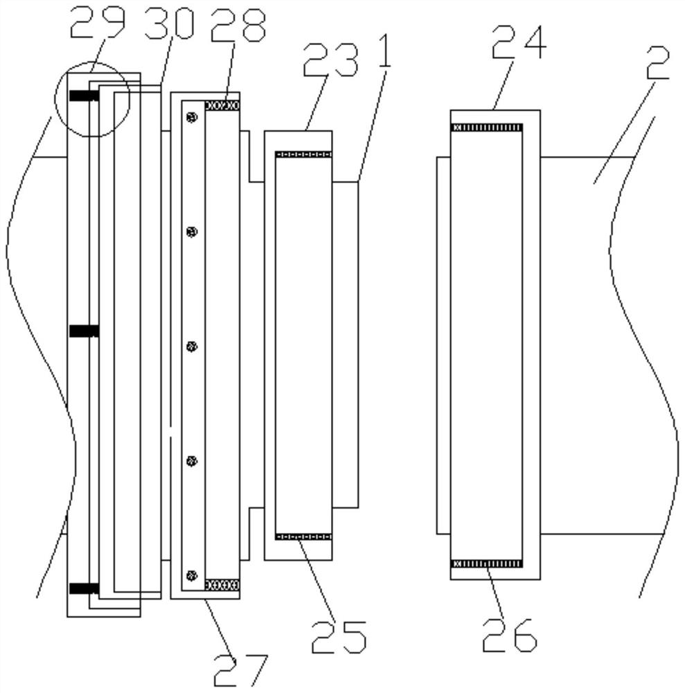
[0034] Such as Figure 3-4 As shown, the sealing mechanism includes a first cylinder 23 fixedly sleeved on the oil supply pipe seat 1 and a second cylinder 24 fixedly sleeved on the nozzle seat 2, the first cylinder The diameter of 23 is smaller than the diameter of the second cylinder 24, and the first cylinder 23 is inserted into the second cylinder 24, and the inner wall of the first cylinder 23 is pasted with a high temperature resistant first sealing ring 25, The nozzle seat 2 is inserted into the first cylinder 23, and the first sealing ring 25 wraps the outer surface of the nozzle seat 2, and the second sealing ring 26 is pasted on the inner wall of the second cylinder 24. The second sealing ring 26 wraps the outer surface of the first cylinder 23, the oil supply pipe seat 1 is fixedly provided with a third cylinder 27, and the inner wall of the third cylinder 27 is pasted with a third sealing ring 28, The second cylinder 24 is inserted into the third cylinder 27, and ...
Embodiment 3
[0037] Such as Figure 3-4 As shown, the anti-screw fall-off mechanism includes a fourth cylinder 29 fixedly sleeved on the oil supply pipe seat 1, and a fifth cylinder 30 is sleeved inside the fourth cylinder 29, and the fifth cylinder 30 is sleeved inside the fourth cylinder 29. The cylinder 30 is sleeved on the third cylinder 27 through a spring mechanism, the spring mechanism includes a spring 31, the inner wall of the fourth cylinder 29 is provided with a spring arrangement groove 32, and one end of the spring 31 is fixed on the The other end of the spring 31 is fixed on the fifth cylinder 30 .
[0038] Through the above scheme of the present invention, the beneficial effect is: before the screw is installed, the handle manually squeezes the fifth cylinder 30 to make the spring shrink, and the fifth cylinder 30 is slowly received into the fourth cylinder 29, at this time It is convenient for the screws to fix the third cylinder 27 and the second cylinder 24. After the fi...
PUM
 Abstract
Description
Claims
Application Information