Supercharge Your Innovation With Domain-Expert AI Agents!

Centrifugal pump capable of reducing clearance leakage flow

A centrifugal pump and gap technology, which is applied to parts, pumps, and pump devices of elastic fluid pumping devices, can solve the problems of centrifugal pumps such as small size, energy loss, and hydraulic efficiency reduction, and achieve the goal of avoiding gap leakage Effect

Pending Publication Date: 2022-04-05
太仓市凯福士机械有限公司
View PDF0 Cites 0 Cited by
  • Summary
  • Abstract
  • Description
  • Claims
  • Application Information

AI Technical Summary

Problems solved by technology

In order to reduce the volume and size of the centrifugal pump, the subsequent problem is that the centrifugal pump is small in size, resulting in the impeller at high speed, there is a tip clearance in the half-open and fully-open centrifugal pumps; due to the blade pressure surface The pressure is higher than the pressure on the suction surface, so that this part of the liquid flow bypasses the tip edge and enters the axial gap between the casing and the blade, forming a leakage flow at the tip gap of the blade, and finally returns to the impeller inlet. There is always a part of the liquid flow in the gap circulation, resulting in energy loss, this flow is called gap leakage flow, resulting in reduced hydraulic efficiency and axial force problems

Method used


Image

  • Centrifugal pump capable of reducing clearance leakage flow
  • Centrifugal pump capable of reducing clearance leakage flow
  • Centrifugal pump capable of reducing clearance leakage flow

Examples


Embodiment 1

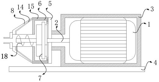
[0023] refer to Figure 1-4 . This embodiment provides a centrifugal pump for reducing gap leakage flow, including: a motor 1 , a rotating shaft 2 , a casing 3 , a bottom plate 4 , a rear cover 5 , a volute 6 , an impeller 7 and a pump cover 8 .

[0024] The casing 3 is arranged on the upper surface of the bottom plate 4, the motor 1 is arranged inside the casing 3, the opening of the casing 3 is arranged horizontally, and the rear cover 5 is connected to the casing 3 The rear side of the volute 6 is arranged to connect the rear cover 5, the pump cover 8 is connected to the front side of the pump cover 8, the upper surface of the volute 6 is provided with a water outlet, and the A water inlet is provided on the front side of the pump cover 8 , and the rotating shaft 2 is connected to the motor 1 and extends into the casing 3 and the pump cover 8 .

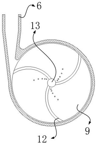
[0025] The impeller 7 is arranged in the volute 6, and the impeller 7 includes a rotating disk 9, a number of first-stage blade...

Embodiment 2

[0038] refer to Figure 1-4 . In one preferred embodiment, the second-stage blades 11 and the third-stage blades 12 are arranged at intervals in relative positions, and the first-stage blades 10 and the second-stage blades 11 overlap each other in relative positions.

[0039] Wherein a preferred embodiment, the secondary blade 11 is provided with several microchannels 19, the inlet of the microchannel 19 is arranged on the front side of the secondary blade 11, and the outlet is arranged on the rear side of the rotating disk 9 and The position corresponding to the entrance of the micro channel 19 .

[0040] Wherein a preferred embodiment, the micro-channel 19 is divided into the first half and the second half, the first half of the micro-channel 19 and the second half of the micro-channel 19 are inclined, the entrance of the micro-channel 19 and The relative positions of the outlets are all lower than the relative positions of the highest points of the micro-channels 19 .

...


PUM


Abstract

The centrifugal pump comprises a motor, a rotating shaft, a machine shell, a bottom plate, a rear cover plate, a volute, an impeller and a pump cover, the rotating shaft is connected with the motor and extends into the machine shell and the pump cover, the impeller is arranged in the volute and comprises a rotating disc, a plurality of first-stage blades, a plurality of second-stage blades, a third-stage blade and a connecting opening, and the rotating shaft penetrates through the connecting opening and is connected with the bottom plate. The first-stage blades and the second-stage blades are arranged on the front side of the rotating disc, the third-stage blades are arranged on the rear side of the rotating disc, the first-stage blades and the second-stage blades are arranged at intervals, the first-stage blades are longer than the second-stage blades, the top ends of the first-stage blades are arranged on the outer edge of the rotating disc, and the tail ends of the second-stage blades are arranged on the edge of the connecting opening. The top ends of the third-stage blades are arranged on the outer edge of the rotating disc, the tail ends of the third-stage blades are arranged on the edge of the connecting opening, the pump cover is provided with a plurality of first transfer channels along the pump cover shell, the volute is axially provided with a plurality of second transfer channels, and the first transfer channels and the second transfer channels are in one-to-one correspondence and are in one-to-one connection.

Description

technical field [0001] The invention relates to the field of centrifugal pumps, in particular to a centrifugal pump for reducing gap leakage flow. Background technique [0002] A centrifugal pump is a pump that transports liquid by the centrifugal force generated when the impeller rotates. In order to reduce the volume and size of the centrifugal pump, the subsequent problem is that the centrifugal pump is small in size, resulting in the impeller at high speed, there is a tip clearance in the half-open and fully-open centrifugal pumps; due to the blade pressure surface The pressure is higher than the pressure on the suction surface, so that this part of the liquid flow bypasses the tip edge and enters the axial gap between the casing and the blade, forming a leakage flow at the tip gap of the blade, and finally returns to the impeller inlet. There is always a part of the liquid flow in the gap circulation, resulting in energy loss, this flow is called gap leakage flow, resu...

Claims


Application Information

Patent Timeline
IPC IPC(8): F04D13/06F04D29/42F04D29/22F04D29/24
Inventor 高峰
Owner 太仓市凯福士机械有限公司
Features
  • R&D
  • Intellectual Property
  • Life Sciences
  • Materials
  • Tech Scout
  • Unparalleled Data Quality
  • Higher Quality Content
  • 60% Fewer Hallucinations
Learn More