Distributed optical fiber sensor high-temperature dynamic calibration system and method

A distributed optical fiber and dynamic calibration technology, which is applied in the direction of instruments, thermometers, scientific instruments, etc., can solve problems such as difficult to adapt to the dynamic high temperature environment and doubtful temperature measurement accuracy, so as to reduce social fire safety hazards, reduce material costs, reduce cost effect

Pending Publication Date: 2022-04-05
应急管理部天津消防研究所 +1
View PDF0 Cites 2 Cited by
  • Summary
  • Abstract
  • Description
  • Claims
  • Application Information

AI Technical Summary

Problems solved by technology
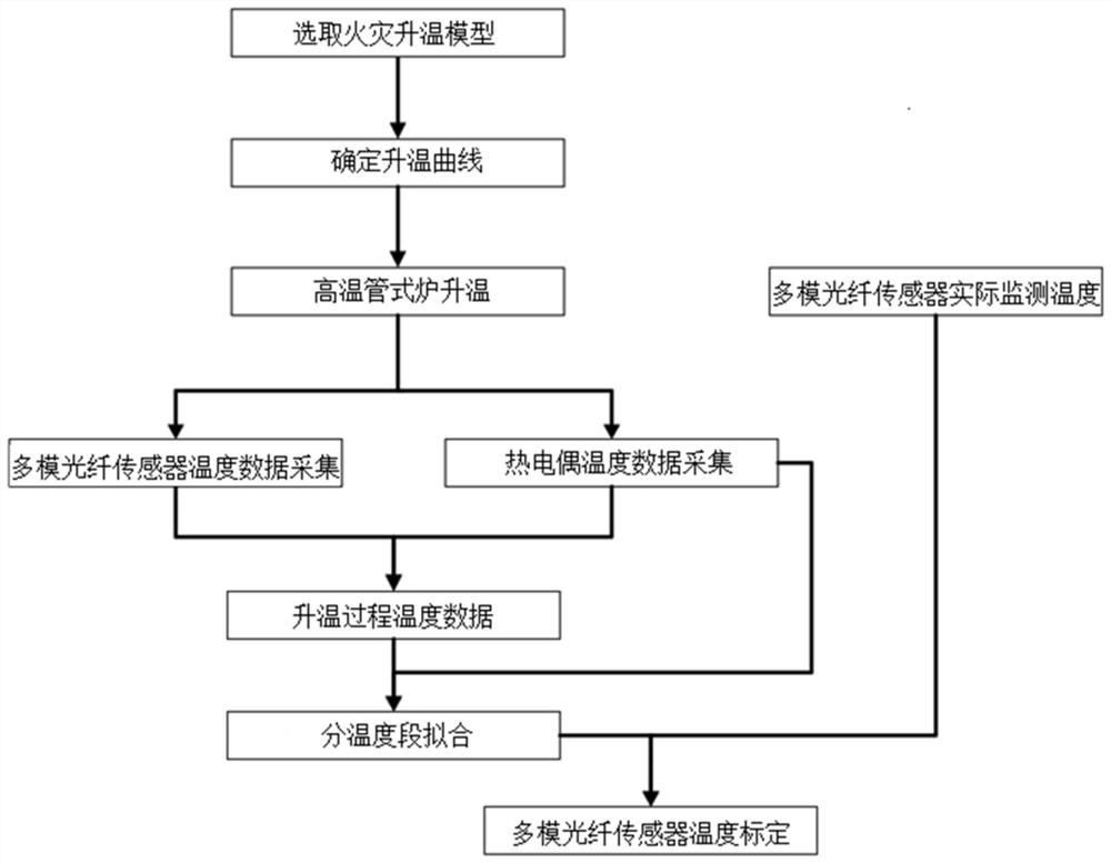
Although the fiber is calibrated at high temperature, the constant temperature calibration method is still used
In addition, different high-temperature temperature sections are not defined to implement the calibration of the fiber optic sensor in different temperature sections and temperature intervals. It may be difficult to adapt to the dynamic high-temperature environment, and the temperature measurement accuracy in the fire warning scene is doubtful.
[0010] In summary, there is currently no efficient and accurate high-temperature dynamic calibration system and method for optical fiber sensors

Method used


Image

  • Distributed optical fiber sensor high-temperature dynamic calibration system and method
  • Distributed optical fiber sensor high-temperature dynamic calibration system and method
  • Distributed optical fiber sensor high-temperature dynamic calibration system and method

Examples


Embodiment Construction

[0040] The present invention will be described in further detail below in conjunction with the accompanying drawings and specific embodiments. It should be understood that the specific embodiments described here are only used to explain the present invention, not to limit the present invention.

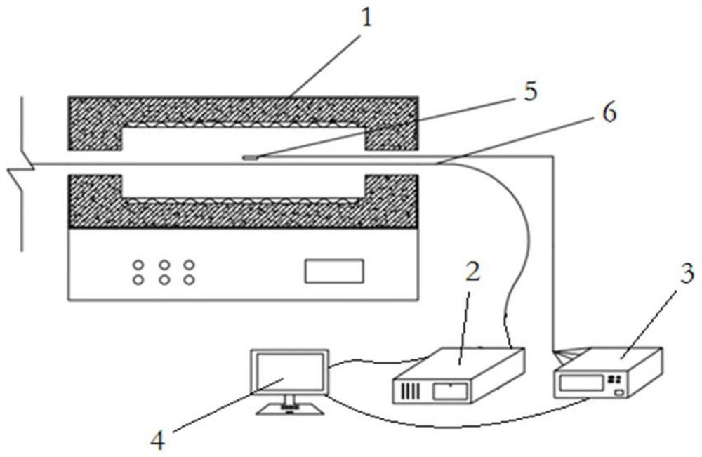
[0041] See figure 2 , the present invention provides a high-temperature dynamic calibration system for distributed optical fiber sensors, including a high-temperature tube furnace 1, a temperature demodulator 3, a DTS Raman optical fiber demodulator 2 and a computer 4, and the temperature demodulator 3 in this embodiment is Agilent temperature demodulator; K-type thermocouple 5 and multimode optical fiber sensor 6 are placed in high temperature tube furnace 1, thermocouple 5 is connected to temperature demodulator, multimode fiber sensor 6 is connected to DTS Raman fiber interrogator 2 connection; both the temperature demodulator 3 and the DTS Raman fiber demodulator 2 are connected...


PUM

PropertyMeasurementUnit
Lengthaaaaaaaaaa

Abstract

The invention discloses a distributed optical fiber sensor high-temperature dynamic calibration system and method.The calibration system comprises a high-temperature tube furnace, a temperature demodulator, a DTS Raman optical fiber demodulator and a computer, a thermocouple and a multimode optical fiber sensor are placed in the high-temperature tube furnace, the thermocouple is connected with the temperature demodulator, and the temperature demodulator is connected with the DTS Raman optical fiber demodulator; the multimode optical fiber sensor is connected with the DTS Raman optical fiber demodulator; the temperature demodulator and the DTS Raman optical fiber demodulator are connected with the computer; the multi-mode optical fiber sensors penetrate through the high-temperature tube furnace in a reciprocating mode in an S-shaped mode, the turning positions of the multi-mode optical fiber sensors are arranged outside the high-temperature tube furnace, at least four sections of the multi-mode optical fiber sensors are arranged in the high-temperature tube furnace, and the mechanical tension state of each section of the multi-mode optical fiber sensors in the high-temperature tube furnace is zero; and a thermocouple is correspondingly arranged on one side of each section of multimode optical fiber sensor in the high-temperature tube furnace.

Description

technical field [0001] The invention relates to the field of temperature calibration of sensors, in particular to a high-temperature dynamic calibration system and method for distributed optical fiber sensors. Background technique [0002] The distributed optical fiber temperature measurement system (DTS) based on Raman scattering is a new type of temperature measurement system developed by using the influence of temperature on the intensity of Raman backscattered light. Due to the small size of the optical fiber sensor, it can be flexibly arranged and resist electromagnetic interference. With the advantages of long-distance continuous temperature measurement, the system has been widely used in various high-temperature monitoring and fire early warning projects. However, the commonly used optical fiber temperature sensor calibration method still stays in the constant temperature calibration stage, and its calibration parameters are mostly Laboratory parameters are difficult ...

Claims


Application Information

Patent Timeline
IPC IPC(8): G01K15/00
Inventor 王岚曲冠华薛岗孟弘融王俊胜任蕾赵壁刘刚方磊
Owner 应急管理部天津消防研究所
Why Eureka
Try Eureka