Error calibration method of five-axis dispensing machine based on industrial camera
An error calibration and industrial camera technology, applied in image data processing, instruments, calculations, etc., can solve the problems of low execution efficiency, long time required, expensive, etc., and achieve the effect of simplifying the calibration process and reducing the cost of calibration
- Summary
- Abstract
- Description
- Claims
- Application Information
AI Technical Summary
Problems solved by technology
Method used
Image

Examples
Embodiment 1
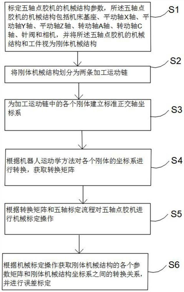
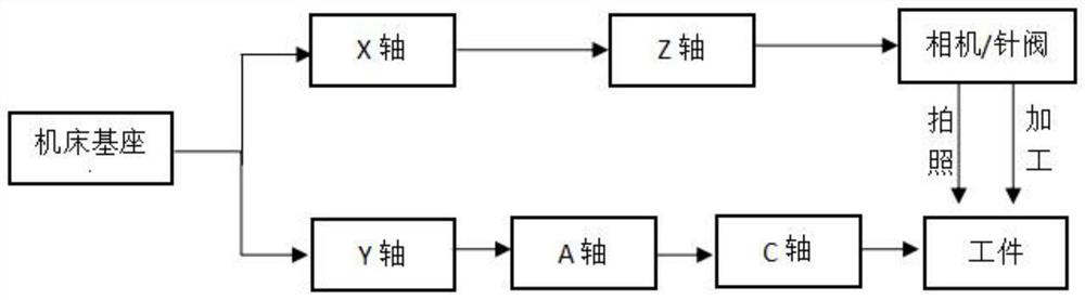
[0105] An error calibration method for a five-axis dispensing machine based on an industrial camera in this embodiment, such as figure 1 As shown, the purpose of mechanical calibration in this embodiment is to calibrate the mechanical geometry parameters of the five-axis dispenser, calculate various error data existing in the five-axis equipment, and establish the workpiece coordinate system, camera coordinate system, and machine tool coordinate system. the transformation matrix. Such as figure 2 As shown, the five-axis dispensing machine is mainly composed of a machine base, three translation axes (X axis, Y axis, Z axis), and two rotation axes (A axis, C axis). Through the link between the base of the machine tool and each axis, and the connection between the axes, a processing kinematic chain is formed to realize five-axis linkage. During the movement process, based on the idea of robot kinematics, the machine tool base, motion axis, glue valve, workpiece, and camera o...
Embodiment 2
[0107] This embodiment is further optimized on the basis of embodiment 1.
[0108] Other parts of this embodiment are the same as those of Embodiment 1, so details are not repeated here.
Embodiment 3
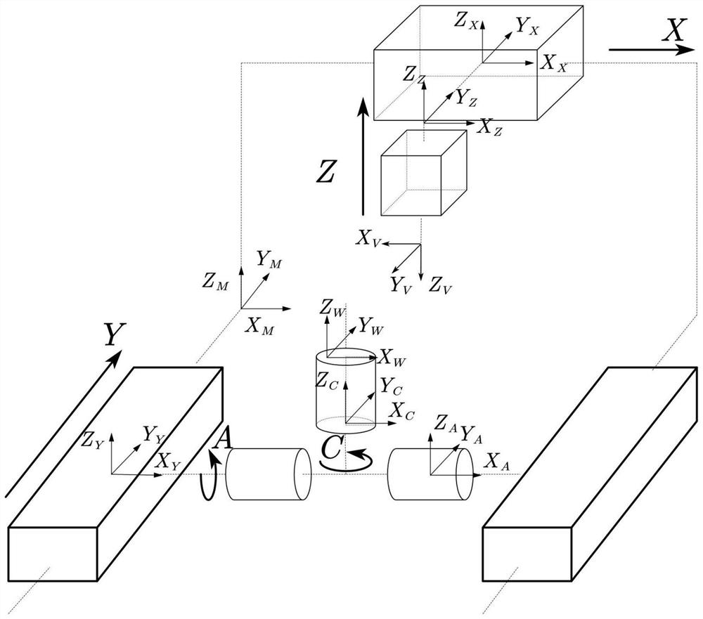
[0110] This embodiment is further optimized on the basis of embodiment 1, such as image 3 As shown, the machine tool base coordinate system {M} can be used as a reference coordinate system for all coordinate system poses, and the coordinate origin is located at the machine origin; the workpiece coordinate system {W} does not exist between the calibration plate and the workbench during calibration. For relative displacement, the workpiece coordinate system is considered to be the same as the calibration plate coordinate system, and the two are collectively referred to as the workpiece coordinate system in the following; the coordinate system {X} of the X axis, the coordinate X axis is parallel to the actual X translation axis, and the origin coincides with {M} ;The coordinate system {Y} of the Y axis coincides with {W} when the A axis and the C axis are not rotated; the coordinate system {Z} of the Z axis, the coordinate Z axis is parallel to the actual Z translation axis, and ...
PUM
 Abstract
Description
Claims
Application Information