Eureka AIR delivers breakthrough ideas for toughest innovation challenges, trusted by R&D personnel around the world.

Labor-saving device for bathroom production mold

A mold and hoisting technology, applied in the field of mold manufacturing, can solve the problem that the auxiliary grasping device cannot be invested on a large scale, and achieve the effect of reducing labor intensity and improving work efficiency

Pending Publication Date: 2022-04-08
广东统用智能家居有限公司
View PDF1 Cites 0 Cited by
  • Summary
  • Abstract
  • Description
  • Claims
  • Application Information

AI Technical Summary

Problems solved by technology

[0003] In the sanitary ware production workshop, a series of operations such as stamping, flipping, and demoulding of the mold are required. The mold itself is heavy, and these tasks cannot be completed manually, and traditional robotic arms and other auxiliary grabbing devices cannot be used on a large scale. On the production line, the patent No. CN108043989B proposes a mold stamping device for easy demoulding. , after the second motor starts, it will drive the rotation of the first screw, and the rotation of the first screw will drive the slide bar to slide up and down on both sides of the vertical bar. Compared with the traditional way of relying on manpower to take out the punched mold body, this demoulding method is more convenient and quicker, and can greatly reduce people's labor intensity, but this solution only solves the problem of how to save labor during the demoulding process. However, the problems of different height operations and mold turning operations in actual mold manufacturing have not been solved, so there are certain limitations in actual operation

Method used


Image

  • Labor-saving device for bathroom production mold
  • Labor-saving device for bathroom production mold
  • Labor-saving device for bathroom production mold

Examples


Embodiment Construction

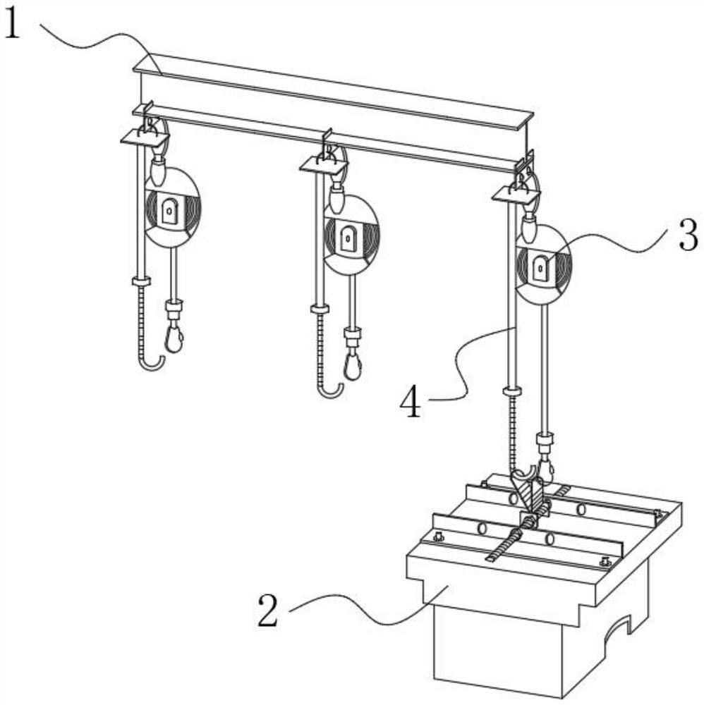
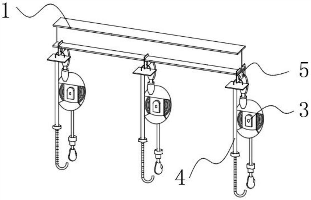
[0028] In order to better understand the purpose, structure and function of the present invention, a labor-saving device for sanitary ware production molds of the present invention will be described in further detail below in conjunction with the accompanying drawings.

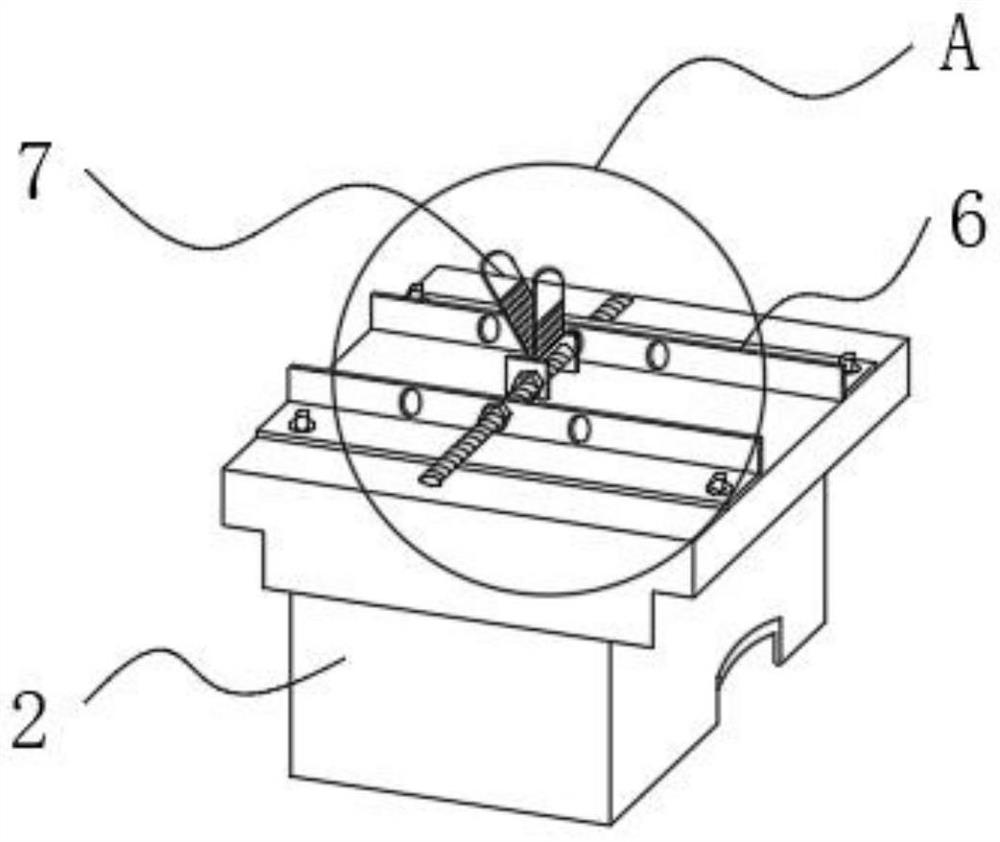
[0029] see Figure 1-7 , the present invention: a mold labor-saving device for sanitary ware production, comprising an I-shaped steel frame 1 and a mold 2, the I-shaped steel frame 1 is provided with a clip 5, and the clip 5 is respectively hoisted with a spring balancer 3 and a telescopic fixed 4, a fixed locking structure 6 is installed on the top of the mold 2, and one end of the spring balancer 3 and the telescopic fixer 4 are both socketed with the fixed locking structure 6;

[0030] Wherein, the fixed locking structure 6 includes two sets of L-shaped plates 61 and threaded columns 62, the L-shaped plates 61 are fixed on the top panel of the mold 2 by bolts 64, and the two sets of L-shaped plates 61 are o...


PUM


Abstract

The invention relates to the technical field of mold manufacturing, in particular to a labor-saving device for a bathroom production mold, which comprises an I-shaped steel frame and a mold, a clamping piece is arranged on the I-shaped steel frame, a spring balancer and a telescopic fixer are respectively hung on the clamping piece, and a fixed locking structure is mounted at the top of the mold. One end of the spring balancer and one end of the telescopic fixator are both connected with the fixing and locking structure in a sleeving mode, the fixing and locking structure comprises two L-shaped plates and threaded columns, a hoisting structure is arranged on the threaded columns located in the two L-shaped plates, the hoisting structure comprises two limiting blocks, and a first hoisting plate and a second hoisting plate are fixedly connected between the two limiting blocks; by using the fixed locking structure and the hoisting structure and applying the lifting force of the spring balancer, the labor intensity of workers is greatly reduced, the length of the telescopic fixer can be manually adjusted to adapt to operation with different height requirements, and a better balancing effect is achieved by matching with the action of the first hoisting plate and the second hoisting plate; the labor is saved; and meanwhile, the production efficiency is further improved.

Description

technical field [0001] The invention relates to the technical field of mold manufacturing, in particular to a labor-saving device for sanitary ware production molds. Background technique [0002] Mold, various molds and tools used in industrial production for injection molding, blow molding, extrusion, die-casting or forging forming, smelting, stamping, etc. pieces of tools. Widely used in blanking, die forging, cold heading, extrusion, powder metallurgy parts pressing, pressure casting, and compression molding or injection molding of engineering plastics, rubber, ceramics and other products. [0003] In the sanitary ware production workshop, a series of operations such as stamping, flipping, and demoulding of the mold are required. The mold itself is heavy, and these tasks cannot be completed manually, and traditional robotic arms and other auxiliary grabbing devices cannot be used on a large scale. On the production line, the patent No. CN108043989B proposes a mold stamp...

Claims


Application Information

Patent Timeline
Patent Type & Authority Applications(China)
IPC IPC(8): B21D37/14
Inventor 姜从高陈大航陈慕璇苏小英周鸿杰苏国亮林桂彬
Owner 广东统用智能家居有限公司
Why Eureka
Eureka Blog
Learn More