Aerospace composite material grating structure laying method

A composite material and grid structure technology, applied in the aerospace application field of composite materials, can solve the problems of poor fiber infiltration and high fiber content, and achieve the effects of avoiding thickness accumulation, improving grid structure, and avoiding fiber accumulation.

Pending Publication Date: 2022-04-08
上海瓴荣材料科技有限公司 +1
View PDF0 Cites 0 Cited by
  • Summary
  • Abstract
  • Description
  • Claims
  • Application Information

AI Technical Summary

Problems solved by technology

like figure 1 As shown, a big disadvantage of this method is that there is multi-directional fiber accumulation at the intersection of the grid, so that the height at this point is often twice or even more than twice that of the ribs at the non-intersection. If Forcibly compressing its height to the same height will cause the fiber content at the intersection to be too high, resulting in poor fiber infiltration due to too little resin, which will become a weak point of the structure and fail

Method used


Image

  • Aerospace composite material grating structure laying method
  • Aerospace composite material grating structure laying method
  • Aerospace composite material grating structure laying method

Examples


Embodiment Construction

[0023] The technical solution of the present invention will be further described below in conjunction with the accompanying drawings.

[0024] The method for laying up a grid structure of aerospace composite materials includes the following steps: for multiple ribs in the same direction and the same layer of fiber strips, the intersections selected for the design of the layup avoidance should be staggered from each other.

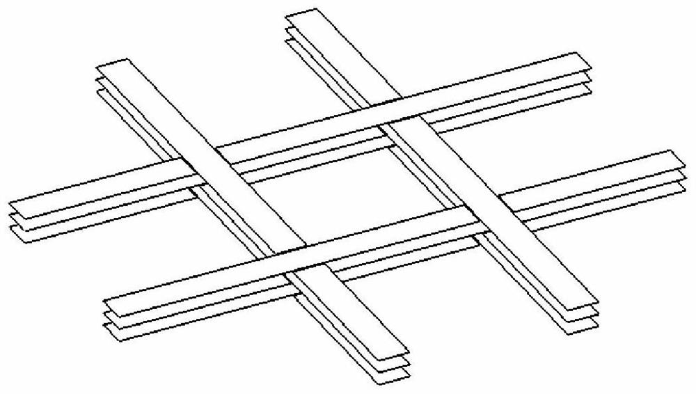
[0025] Such as figure 2 As shown, taking a 2×2 grid with 3 layers as an example, according to the definition of traditional continuous layering, the number of layers accumulated at the four intersections is 6 layers.

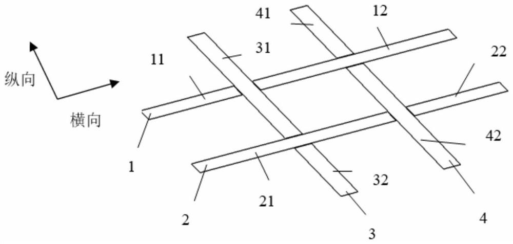
[0026] Such as image 3 As shown, in the first layer of the 2×2 grid, the first transverse rib 1 is cut and divided into 11 layers and 12 layers at the intersection with the first longitudinal rib 3; The intersection of two longitudinal ribs 4 is cut and divided into 21 layers and 22 layers; the first longitudinal rib 3 is cut and divided ...


PUM


Abstract

The invention discloses an aerospace composite material grating continuous clearance laying layer structure which is characterized in that by taking laying of three layers of 2 * 2 gratings as an example, in a first layer, four intersections formed by four ribs are cut off in sequence, in a second layer, four intersections are cut off in sequence, and then the three layers of gratings are overlapped, so that in the whole structure, the three layers of gratings are overlapped in sequence; the ribs located at the same position can be cut off at the same intersection every other layer, so that a clearance structure is formed; according to the scheme, the problem of thickness accumulation at the intersection point in a traditional layering mode is effectively solved, the fiber accumulation condition is avoided, and the failure probability is effectively reduced.

Description

technical field [0001] The invention relates to the aerospace application of composite materials, in particular to a method for laying layers of a grid structure of aerospace composite materials. Background technique [0002] The composite grid structure not only inherits the advantages of high specific strength, high specific stiffness, and good structural designability of the composite structure, but also has its own inherent environmental robustness, low cost, and high effectiveness. of great importance. [0003] Lattice structures can be manufactured in a number of ways, including, using continuous fiber cross-ply. Such as figure 1 As shown, a big disadvantage of this method is that there is multi-directional fiber accumulation at the intersection of the grid, so that the height at this point is often twice or even more than twice that of the ribs at the non-intersection. If Forcibly compressing its height to the same height will lead to too high fiber content at the ...

Claims


Application Information

Patent Timeline
Patent Type & Authority Applications(China)
IPC IPC(8): B29C70/30B29C70/22B29L31/30
Inventor 陈亨津荣一鸣杨琨
Owner 上海瓴荣材料科技有限公司
Why Eureka
Try Eureka