Environment-friendly sludge treatment equipment for sewage treatment plant

A sewage treatment plant, sludge treatment technology, applied in the direction of sludge treatment, water/sludge/sewage treatment, cleaning methods and tools, etc., can solve the problems of time-consuming, laborious and inconvenient manual cleaning of sludge, and achieve shortened cleaning time, cleaning operation is convenient, and the effect of improving work efficiency

Pending Publication Date: 2022-04-08
江苏环保产业技术研究院股份公司 +1
View PDF8 Cites 0 Cited by
  • Summary
  • Abstract
  • Description
  • Claims
  • Application Information

AI Technical Summary

Problems solved by technology

[0006] The invention provides an environment-friendly sludge treatment equipment for sewage treatment p

Method used


Image

  • Environment-friendly sludge treatment equipment for sewage treatment plant
  • Environment-friendly sludge treatment equipment for sewage treatment plant
  • Environment-friendly sludge treatment equipment for sewage treatment plant

Examples


no. 1 example

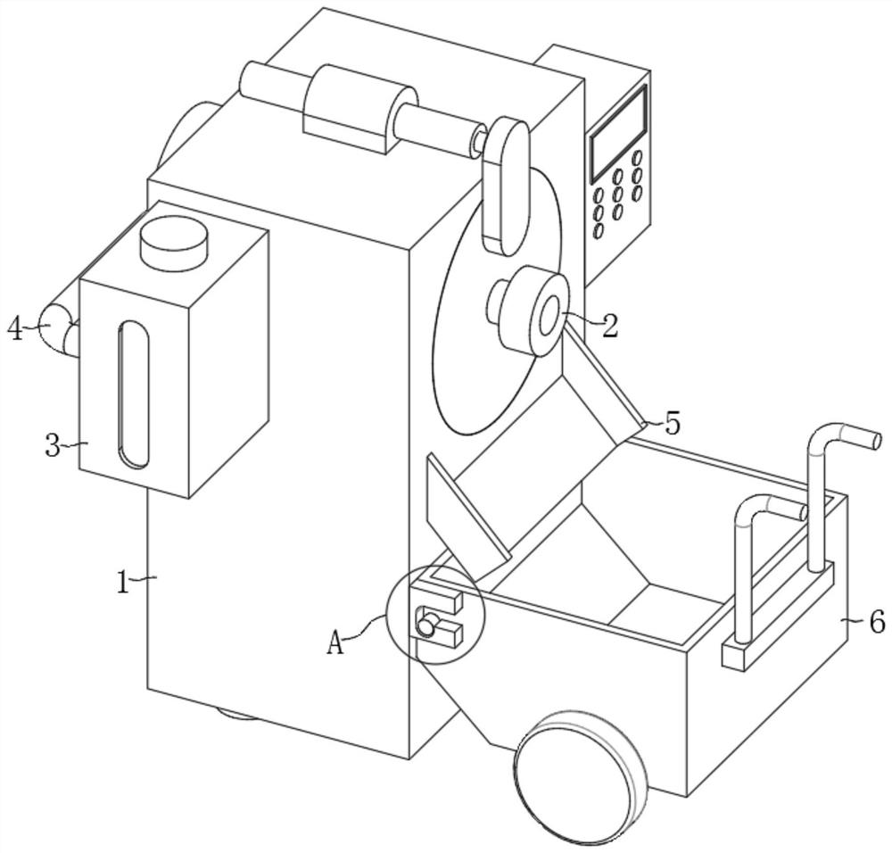
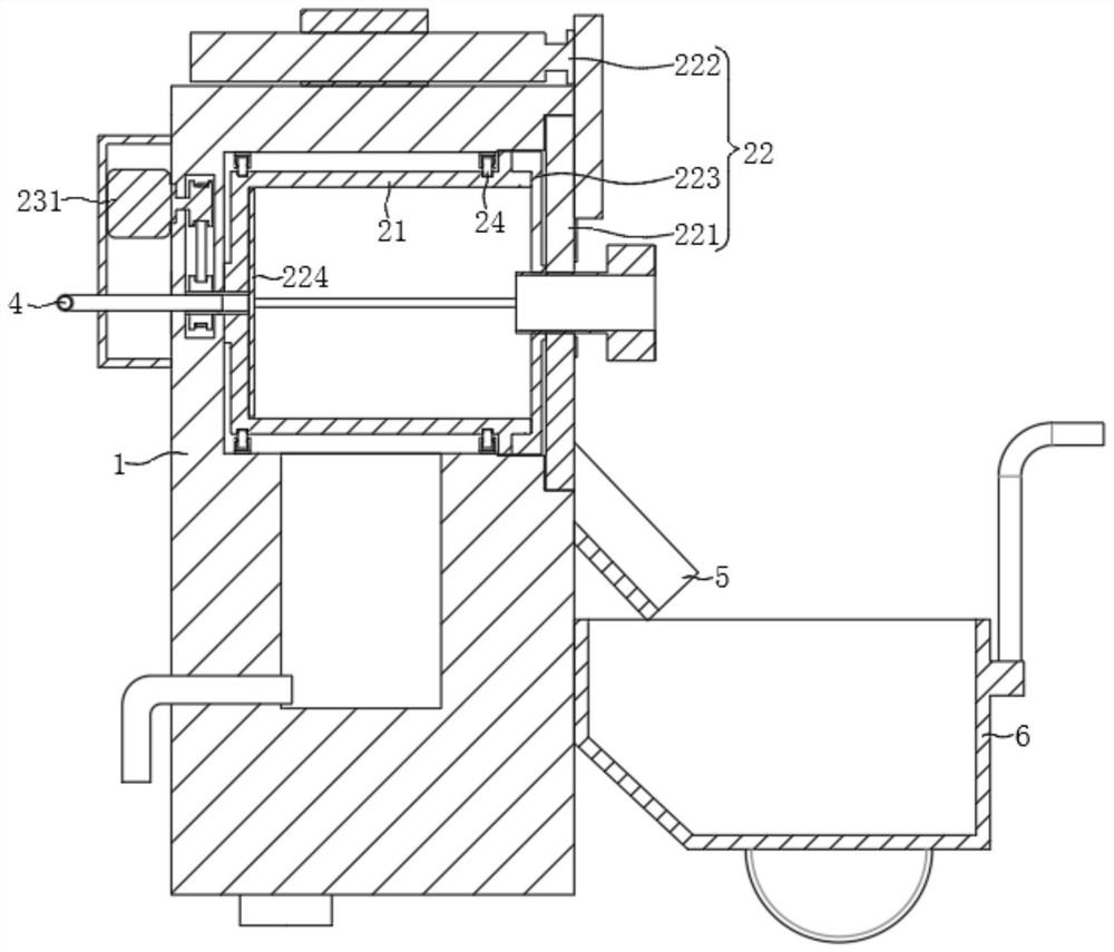
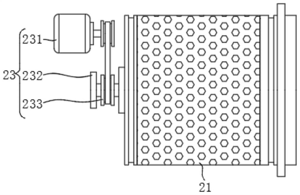
[0046] Please refer to figure 1 , figure 2 , image 3 , Figure 4 , Figure 5 and Figure 6 ,in, figure 1 Schematic diagram of the structure of the first embodiment of the sludge treatment equipment for environment-friendly sewage treatment plants provided by the present invention; figure 2 for figure 1 The schematic diagram of the internal structure of the body shown; image 3 for figure 1 The schematic diagram of the external structure of the centrifugal structure shown; Figure 4 for image 3 Exploded schematic diagram of the centrifugal structure shown; Figure 5 for figure 1 The structural schematic diagram of the back of the housing shown; Figure 6 for figure 1 The enlarged schematic diagram of part A is shown. Environmentally friendly sludge treatment equipment for sewage treatment plants, including:

[0047] body 1;

[0048] Centrifugal structure 2, the centrifugal structure 2 is arranged inside the body 1, the centrifugal structure 2 includes a cent...

no. 2 example

[0061] Please refer to Figure 7-9 , based on the first embodiment of the present invention, an environment-friendly sewage treatment plant sludge treatment equipment, the second embodiment of the present invention provides another environment-friendly sewage treatment plant sludge treatment equipment, wherein the second embodiment It does not hinder the independent implementation of the technical solution of the first embodiment.

[0062] Specifically, the present invention provides another environment-friendly sewage treatment plant sludge treatment equipment with the following differences:

[0063] One side of the outer sealing cover 221 is provided with an introduction structure 7, the introduction structure 7 includes a mixing cylinder 71, one side of the mixing cylinder 71 is fixedly installed with one side of the outer sealing cover 221, and the mixing cylinder 71 is equipped with a screw rotating part 72, and the outside of the mixing cylinder 71 is fixedly equipped w...


PUM


Abstract

The invention provides environment-friendly sludge treatment equipment for a sewage treatment plant. The environment-friendly sludge treatment equipment for the sewage treatment plant comprises a machine body; the centrifugal structure is arranged in the machine body, and the centrifugal structure comprises a centrifugal roller for centrifugally dewatering sludge and a sealing assembly for sealing one side of the centrifugal roller. According to the environment-friendly sludge treatment equipment for the sewage treatment plant, the sealing assembly is arranged on the outer side of the centrifugal roller and is mainly used for sealing the outer side of the centrifugal roller, meanwhile, the function of automatically cleaning sludge in the centrifugal roller can be achieved, and after sludge dewatering is completed, the telescopic assembly extends, so that the sludge in the centrifugal roller can be recycled. Finally, the cleaning piece can horizontally move outwards in the centrifugal roller, then the sludge flows outwards into the collecting vehicle, automatic sludge cleaning is completed, manual cleaning operation is changed, and sludge cleaning operation is more convenient, more labor-saving and faster.

Description

technical field [0001] The invention relates to the field of sludge treatment, in particular to an environment-friendly sludge treatment equipment for sewage treatment plants. Background technique [0002] Sludge is a solid precipitated substance produced in the water and sewage treatment process, and sludge treatment involves reducing, stabilizing, and harmless sludge such as concentration, conditioning, dehydration, stabilization, drying, or incineration. In the process of processing, the higher the degree of sewage treatment, the more sludge residues will be generated to be treated. For modern sewage treatment plants, sludge treatment and disposal have become the most complicated and costly in the operation of sewage treatment systems. a part of. [0003] In the process of sludge treatment, special sludge treatment equipment is required. When dehydrating sludge, sludge centrifugal dehydration equipment is generally used. The centrifugal force generated when the drum rota...

Claims


Application Information

Patent Timeline
IPC IPC(8): C02F11/127B08B9/087
Inventor 高鸣毕军李冰马志盼毛小柳葛苏苏张琳娜殷井云刘超
Owner 江苏环保产业技术研究院股份公司
Why Eureka
Try Eureka